background image

English

2. CABLE CONNECTION

13

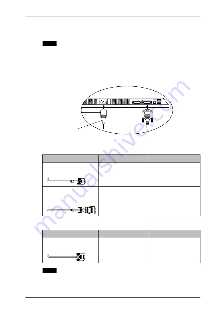
2-2. Connecting the Signal Cable

NOTE

z

Be sure that the power switches of both the PC and the monitor are OFF.

1.

Plug the signal cable into the connector at the rear of the monitor 
and the other end of the cable into the video connector on the PC.

After connecting, secure the connection with the screw-in fasteners.

Analog Input

Digital Input

NOTE

z

The monitor is not compatible with a Power Mac G4/G5 ADC (Apple Display 
Connector)

Signal Cable

Connector

PC

Signal Cable 
(FD-C16 enclosed)

Video Output Connector / 
D-Sub mini 15 pin

Input Connector (monitor) /  
DVI

z

Standard graphics card

z

Power Macintosh G3 
(Blue & White) / Power 
Mac G4 (VGA)

Signal Cable 
(FD-C16 enclosed) + 
Macintosh Adapter (Optional)

Video Output Connector / 
D-Sub 15 pin

Input Connector (monitor) /  
DVI

z

Macintosh

Signal Cable

Connector

PC

Signal Cable 
(FD-C39 enclosed)

Video Output Connector / 
DVI

Input Connector (monitor) /  
DVI

z

Digital graphics board

z

Power Mac G4/G5 (DVI)

Power Cord

Summary of Contents for EIZO FlexScan L 788 L788 L788

Page 1: ......

Page 2: ...ange without notice ENERGY STAR is a U S registered mark Apple and Macintosh are registered trademarks of Apple Computer Inc VGA is a registered trademark of International Business Machines Corporatio...

Page 3: ...g Two PCs to the Monitor 16 3 ScreenManager 18 3 1 How to use the ScreenManager 18 3 2 ScreenManager Adjustments and Settings 19 3 3 Useful Functions 21 4 ADJUSTMENT 23 4 1 Screen Adjustment 23 4 2 Di...

Page 4: ...ocation of the Caution Statements WARNING If the unit begins to emit smoke smells like something is burning or makes strange noises disconnect all power connections immediately and contact your dealer...

Page 5: ...damaged unit may result in fire or electric shock Set the unit in an appropriate location Not doing so may result in fire electric shock or equipment damage z Do not place outdoors z Do not place in t...

Page 6: ...er Touching them may result in electric shock When attaching an arm stand please refer to the user s manual of the arm stand and install the unit securely with the enclosed screws Not doing so may cau...

Page 7: ...the unit laid down or upside down Blocking the ventilation slots prevents proper airflow and may result in fire electric shock or equipment damage Do not touch the plug with wet hands Doing so may res...

Page 8: ...ght of the LCD panel has a fixed life span When the screen becomes dark or begins to flicker please contact your dealer Do not press on the panel or edge of the frame strongly as this may result in da...

Page 9: ...44 standard z Smoothing function incorporated for the adjustment of an enlarged image p 27 z The height adjustable stand incorporated z Ultra slim bezel incorporated z The Portrait Landscape display...

Page 10: ...2 Directly pressing the control button allows you to adjust screen brightness If you choosing the custom color mode you also may adjust screen contrast 3 These buttons are changed to Up Left Right Dow...

Page 11: ...aver se curity system For further information please consult Kensington Technology Group 2855 Campus Drive San Mateo CA 94403 USA Tel 800 650 4242 x3348 Intl 650 572 2700 x3348 Fax 650 572 9675 http w...

Page 12: ...gs Analog Input Digital Input Only the following resolutions with frequency can be displayed on this model Resolution Frequency Dot Clock Remarks 640 480 67 Hz 135 MHz Max Apple Macintosh 640 480 85 H...

Page 13: ...he monitor is not compatible with a Power Mac G4 G5 ADC Apple Display Connector Signal Cable Connector PC Signal Cable FD C16 enclosed Video Output Connector D Sub mini 15 pin Input Connector monitor...

Page 14: ...the smooth motion of the stand and the Portrait Landscape display 4 Plug the other end of the power cord into a power outlet WARNING Use the enclosed power cord and connect to the standard power outle...

Page 15: ...HOOTING p 36 for advice Whenever finished turn off the PC and the monitor NOTE z When turning on the monitor the kind of the input signal Signal1 or 2 Analog or Digital is displayed for a few seconds...

Page 16: ...r Connecting Examples PC 1 PC 2 Ex 1 Digital DVI Signal Cable FD C39 enclosed Signal Cable FD C16 enclosed D Sub mini 15 pin Analog Ex 2 Analog D Sub mini 15 pin Signal Cable FD C16 enclosed Signal Ca...

Page 17: ...he input to that signal In the case of only one signal being present at either input the monitor automatically detects and displays that signal NOTE z When the 1 or 2 is selected the power saving mode...

Page 18: ...ting icon and press the Enter Button The setting menu appears 3 Use the Control buttons to make all required adjustments and press the Enter Button to save the settings 3 Exiting the ScreenManager 1 T...

Page 19: ...nalog input only and indicates digital input only Main menu Sub menu Reference Screen Clock 4 1 Screen Adjustment p 23 Phase Position Resolution Range Adjustment Smoothing Signal Filter Color Manageme...

Page 20: ...ings Menu Size Change the size of the menu Menu Position Adjust the menu position Menu Off Timer Set the menu displaying time Translucent Set the transparency of the background Orientation Change the...

Page 21: ...monitors when the monitor screen is left on for a long period without use Procedure 1 Select Off Timer in the ScreenManager Others menu 2 Select Enable and press the right and left buttons to adjust...

Page 22: ...lect Power Indicator in the ScreenManager Others menu 2 Select Disable EIZO Logo Appearing Function When switching on the Power Button on the control panel the EIZO logo is displayed for a while If yo...

Page 23: ...ur setting will be lost if you press again now appears and remains on the screen for 5 seconds While the message is on the screen press the Auto Adjustment Button again to automatically adjust the clo...

Page 24: ...k e g OS 2 we recommend setting the desktop pattern to that as shown in the diagram on the following 3 Adjust by using Screen menu in the ScreenManager 1 Vertical bars appear on the screen Use the Clo...

Page 25: ...rect Use the Position adjustment The correct displayed position of the monitor is decided because the number and the position of the pixels are fixed The Position adjustment moves the image to the cor...

Page 26: ...output signal range Dynamic Range of the signal Use the Range Adjustment p 44 of Screen menu This controls the level of output signal range to display the whole color gradation 256 colors Procedure Se...

Page 27: ...isabled when the screen is displayed in the following resolutions 1280 x 1024 The image size is doubled both in horizontally and vertically to i e 1280 x 960 enlarged from 640 x 480 provide clear focu...

Page 28: ...the black area surrounding the displayed image Set the Border Intensity In the Enlarge mode or Full Screen mode the outer area border is usually black Select Border Intensity in the Others menu and ad...

Page 29: ...es represent the current level within the specific adjustment They are available only as a reference tool To create a uniform white or black screen the percentages for each will probably not be the sa...

Page 30: ...d blue 0 100 By adjusting the red green and blue color tones for each mode custom colors can be defined Display a white or gray background image and adjust the Gain NOTE z The values shown in the perc...

Page 31: ...ower consumption of the monitor will change according to the connected devices even if the monitor is in a power saving mode Analog Input This monitor complies with the VESA DPMS p 44 standard and ado...

Page 32: ...Procedure 1 Set the PC s power saving settings 2 Select DVI DMPM in the PowerManager menu Power Saving System 1 Power saving through the PC s off mode is only supported when Manual is selected on the...

Page 33: ...ding on the PC OS or peripherals Please consult the manufacturer of each device about the USB support z Using the USB Rev 2 0 compatible PC or peripherals is recommended z When the monitor is not on t...

Page 34: ...ting USB compliant peripherals to the downstream ports of the monitor Connecting Examples Upstream Ports To Downstream Ports of the PC or Another Hub Upstream port Connect the USB compliant PC or anot...

Page 35: ...electing Hole spacing on the arm mounting 100 mm x 100 mm VESA compliant Supportable Weight Total weight of the monitor without stand and attaching equipment such as a cable T V GS approved arm or sta...

Page 36: ...rol panel Try pressing a key on the keyboard or clicking the mouse p 31 Try turning the PC on z Indicator status Flashing Yellow twice for each Try turning the PC on 2 Error messages shown below will...

Page 37: ...elow This happens when both composite X OR input signal and separate vertical synchronizing signal are input Please select one of the two 9 The screen is too bright or too dark Adjust the Brightness T...

Page 38: ...21 17 Frequency does not change after installing Monitor information file in the attached utility disk on Windows 98 2000 Me XP Use the graphics board s utility software to change the input signal fr...

Page 39: ...as these may cause damage to the cabinet or LCD panel Cabinet To remove stains wipe the cabinet with a soft lightly moistened cloth using a mild detergent Do not spray wax or cleaner directly into the...

Page 40: ...wer Consumption Min 40 W Max 50 W with USB hub Power Saving Mode Less than 2 W for single signal input without USB Input Connector DVI I x 2 connectors Analog Input Signal Sync a Separate TTL Positive...

Page 41: ...nland Ergonomics Approved Analog input Digital input Brightness 100 100 Smoothing 3 Color Mode Custom PowerManager VESA DPMS DVI DMPM Screen Size Full Input Priority 1 Off Timer Disable Menu Settings...

Page 42: ...and Vsync C1 Analog Red 6 DDC Clock SCL 16 Hot Plug Detect C2 Analog Green 7 DDC Data SDA 17 TMDS Data 0 C3 Analog Blue 8 Analog Vertical Sync 18 TMDS Data 0 C4 Analog Horizontal Sync 9 TMDS Data 1 19...

Page 43: ...igital interface The Monitor ON status operation mode and the Active Off status power saving mode are indispensable for the DVI DMPM as the monitor s power mode EIZO MPMS EIZO Monitor PowerManager Sig...

Page 44: ...lows Internet users to closely match colors Temperature Color temperature is a method to measure the white color tone generally indicated in degrees Kelvin At high temperatures the white tone appears...

Page 45: ...e de synchronisation ci dessous Mode Dot Clock MHz Sync Polarity Frequencies H V H kHz V Hz VGA 640 u 480 60 Hz 25 2 Nega Nega 31 5 60 0 VGA TEXT 720 u 400 70 Hz 28 3 Nega Posi 31 5 70 1 Macintosh 640...

Page 46: ...VESA 1024 u 768 85 Hz 94 5 Posi Posi 68 7 85 0 VESA 1152 u 864 75 Hz 108 0 Posi Posi 67 5 75 0 WS 1152 u 900 66 Hz 94 2 Composite Sync Nega 62 0 66 1 WS 1152 u 900 76 Hz 107 5 Composite Sync Nega 71...

Page 47: ...ility Energy z Energy saving mode after a certain time beneficial both for the user and environment z Electrical safety z Emissions Electromagnetic fields z Noise emissions Ecology z The products must...

Page 48: ...ental labelling of personal computers The labelling scheme was developed as a joint effort by the TCO The Swedish Confederation of Professional Employees Svenska Naturskyddsforeningen The Swedish Soci...

Page 49: ...ous system and is toxic in high doses The relevant TCO 99 requirement states that batteries the colour generating layers of display screens and the electrical or electronics components must not contai...

Page 50: ...rence to radio communications However there is no guarantee that interference will not occur in a particular installation If this equipment does cause harmful interference to radio or television recep...

Page 51: ...t zur Aufnahme des Gewichtes vom Bildschirmger t und des spezifizierten Zubeh rs besitzen Das Gewicht des Bildschirmger tes und des Zubeh rs sind in der zugeh renden Bedienungsanleitung angegeben b Di...

Page 52: ...nd All recycling information is placed in the SWICO s website http www swico ch Recycling Information f r Kunden in der Schweiz Alle Informationen zum Thema Recycling finden Sie auf der Homepage des B...

Page 53: ......

Reviews: