background image

16

Chapter 4  Troubleshooting

Chapter 4  Troubleshooting

If a problem still remains after applying the suggested remedies, contact your local dealer.

Common

Problems

Possible cause and remedy

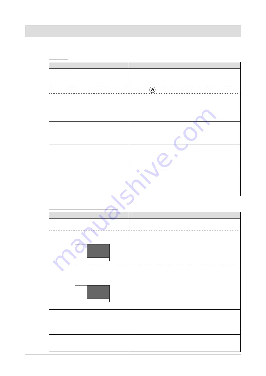
No picture

•  Power indicator does not light.

•  Check whether the power cord is connected correctly.
•  If the problem persists, turn off the power, and then turn 

it on again a few minutes later.

•  Power indicator lights orange.

•  Press 

.

•  Power indicator lights blue.

•  Check whether the power of the connected device is 

turned on.

•  Switch the input signal.
•  Set each adjusting value in [Brightness] and [Contrast] to 

higher level. (see page 14)

The screen is too bright or too dark.

•  Adjust using [Brightness] or [Contrast]. (The LCD 

monitor backlight has a fixed life span. When the screen 
becomes dark or begins to flicker, contact your local 
dealer.) (see page 14)

Green/red/blue/white dots or defective 

dots remain on the screen.

•  This is due to LCD panel characteristics and is not a 

failure.

Interference patterns or pressure marks 

remain on the screen.

•  Leave the monitor with a white or black screen. The 

symptom may disappear.

Afterimages appear.

•  Afterimages are particular to LCD monitors. Avoid 

displaying the same image for a long time.

•  When displaying the same image for extended periods of 

time, please set up the screen saver and/or make use of 
the power saving function.

When displaying on a PC screen

Problems

Possible cause and remedy

The message below appears.

•  This message appears when the signal is not input 

correctly even when the monitor functions properly.

•  This message appears when no signal 

is input. 
               

No
Signal

PC

•  The message shown left may appear, because some 

PCs do not output the signal soon after power-on.

•  Check whether the PC is turned on.
•  Check whether the signal cable is connected properly.

•  The message shows that the input 

signal is out of the specified frequency 
range. 
               

Signal
Error

PC

•  Check whether the signal setting of your PC matches 

the resolution and the vertical frequency settings for the 
monitor. (see page 17, 18, 19) (Current input signal can 
be checked in [Information].)

•  Reboot the PC.
•  Select an appropriate display mode using the graphics 

board’s utility. Refer to the manual of the graphics board 
for details.

Display position is incorrect.

•  Adjust image position using [Position]. (see page 14)

Vertical bars appear on the screen or a 

part of the image is flickering.

•  Adjust using [Clock]. (see page 14)

Whole screen is flickering or blurring.

•  Adjust using [Phase]. (see page 14)

Characters are blurred.

•  This may occur when a non-complying high-resolution 

signal is input. Check the PC settings and change the 
resolution which complies with the monitor.

Summary of Contents for DURAVISION FDV1001

Page 1: ...Important Please read this User s Manual carefully to familiarize yourself with safe and effective usage Please retain this manual for future reference 重要 请仔细阅读用户手册 掌握如何安全 有效地使用本产品 请保留本手册 以备日后参考 ...

Page 2: ......

Page 3: ...orporation PC 9801 and PC 9821 are trademarks of NEC Corporation EIZO the EIZO Logo ColorEdge DuraVision FlexScan FORIS RadiCS RadiForce RadiNET Raptor and ScreenManager are registered trademarks of EIZO NANAO CORPORATION in Japan and other countries All other company and product names are trademarks or registered trademarks of their respective owners SAFETY SYMBOLS This manual and this product us...

Page 4: ...ent damage Use the enclose AC adapter The enclosed AC adapter is for use with this product only Do not use the AC adapter with other equipment Connecting to power sources that do not match the power ratings of the AC adapter may result in fire or electric shock Make sure the power cord meets the following requirements This product does not include a power cord Please provide separately a power cor...

Page 5: ...pter becomes hot during use Do not cover or place anything on top of the AC adapter Do not place the AC adapter on top of things that trap heat Keep the AC adapter away from heat sources and direct sunlight Not doing so may result in fire Do not touch with bare hands Doing so may result in burns The ambient temperature for using the AC adapter should not exceed 40 C 104 F Do not suspend the AC ada...

Page 6: ...on lifetime Refer to Cleaning on the next page The LCD panel is manufactured using high precision technology Although missing pixels or lit pixels may appear on the LCD panel this is not a malfunction Percentage of effective dots 99 99 or higher The backlight of the LCD panel has a fixed lifetime When the screen becomes dark or begins to flicker please contact your local EIZO representative Do not...

Page 7: ...the panel NOTE The optional ScreenCleaner is recommended for cleaning the panel surface If necessary the stains on the panel surface can be removed by moistening part of a soft cloth with water To use the monitor comfortably An excessively dark or bright screen may affect your eyes Adjust the brightness of the monitor according to the environmental conditions Staring at the monitor for a long time...

Page 8: ...troduction 8 1 1 Features 8 1 2 Package Contents 8 Chapter 2 Assembly 9 Chapter 3 Settings and Adjustments 12 3 1 Buttons 12 3 2 Basic Operation and Functions 13 Chapter 4 Troubleshooting 16 Chapter 5 Reference 17 5 1 Specifications 17 5 2 Glossary 20 5 3 Preset Timing 21 LIMITED WARRANTY 22 ...

Page 9: ... scanning frequency 55 Hz 75 Hz FDV1001 Horizontal scanning frequency 24 kHz 32 kHz Vertical scanning frequency 56 Hz 70 5 Hz Video signal S Video Video input connector 1 Applicable Format NTSC PAL SECAM Crosshair display function Displays lines Fine Circle or Broken Line as a reference for the position of the image displayed on the monitor page 15 Video aspect function Alters the display range of...

Page 10: ... 482 1 19 0 0 04 465 18 3 410 16 1 213 8 4 125 4 9 48 1 89 57 2 0 5 2 25 0 02 88 9 0 5 3 5 0 02 146 1 0 5 5 8 0 02 220 1 8 7 0 04 37 1 46 160 6 3 23 0 91 Φ6 4 0 25 Handle mounting holes 6 12 0 24 0 47 Rack mounting holes Video input connector S Video input connector D Sub mini 15 pin connector Power jack DC IN For use with an EIZO AC adapter only ...

Page 11: ... 25 0 02 133 35 0 5 5 3 0 02 190 5 0 5 7 5 0 02 265 1 10 4 0 04 37 5 1 48 146 5 7 88 3 46 430 16 9 26 1 02 272 10 7 22 0 87 47 1 85 26 1 02 Φ6 4 0 25 Handle mounting holes 6 12 0 24 0 47 Rack mounting holes Video input connector S Video input connector D Sub mini 15 pin connector Power jack DC IN For use with an EIZO AC adapter only ...

Page 12: ...by Electric Industries Association EIA 1 Attach the two handles from the front and secure them from the rear using handle mounting screws M5 10 mm 4 pcs Handle 2 Attach the monitor to the rack while holding the handles on both sides and then secure the monitor using screws Rack ATTENTION Screws for attaching the monitor to the rack are not included with this monitor Prepare screws suitable for you...

Page 13: ... each menu and saves the setting or adjustment results 3 button Used to select the setting or adjustment items or to increase or decrease the adjustment values on each menu When the settings menu is not displayed pressing or switches between displaying and not displaying the crosshair 4 button Turns the power on or off 5 Power indicator Indicates monitor s operation status Blue Operating Orange Po...

Page 14: ...stments 3 2 Basic Operation and Functions Basic operation of Setting menu 1 Displaying Setting Menu Press 2 Setting Adjusting 3 Exiting Choose Exit with or and press NOTE Keeping pressed for 2 seconds will also exit the Setting menu ...

Page 15: ...s 1 Clock Adjust this when vertical bars appear Phase Adjust this when the screen appears to flicker or blur Position Adjust this when the display positioning is misaligned Range Adjustment Provides automatic adjustment when you want every color gradients displayed Color Mode 2 1 2 3 Select Color Mode 1 2 3 to adjust the colors of red green and blue in several modes Red Green Blue 0 128 Reset Rese...

Page 16: ...cle Broken Line Displays a crosshair as a reference for the position of the image Fine Circle Broken Line When the settings menu is not displayed pressing or switches between displaying and not displaying the crosshair Color When Fine is selected Black White Red Green When Circle or Broken Line is selected Black White Configures the color of the crosshair Width Narrow Wide Configures the thickness...

Page 17: ...the same image for extended periods of time please set up the screen saver and or make use of the power saving function When displaying on a PC screen Problems Possible cause and remedy The message below appears This message appears when the signal is not input correctly even when the monitor functions properly This message appears when no signal is input No Signal PC The message shown left may ap...

Page 18: ...al Connector S Video DIN mini 4 pin Video Pin jack 1 Input Signal Level S Video DIN mini 4 pin Y 1 0Vp p 75Ω C 0 28Vp p 75Ω Video Pin jack 1 0Vp p 75Ω Power Supply AC adapter AC 100 240VAC 10 50 60Hz 0 3 0 2 A Max Main unit DC 12VDC 10 0 9 A Power Consumption Screen Display On AC adapter AC 13 W or less Main unit DC 11 W or less Power Off AC adapter AC 1 3 W or less Main unit DC 0 5 W or less Dime...

Page 19: ... DIN mini 4 pin Video Pin jack 1 Input Signal Level S Video DIN mini 4 pin Y 1 0Vp p 75Ω C 0 28Vp p 75Ω Video Pin jack 1 0Vp p 75Ω Power Supply AC adapter AC 100 240VAC 10 50 60Hz 0 2 0 15 A Max Main unit DC 12VDC 10 0 7 A Power Consumption Screen Display On AC adapter AC 10 W or less Main unit DC 9 W or less Power Off AC adapter AC 1 3 W or less Main unit DC 0 5 W or less Dimensions Width Height ...

Page 20: ...ini 4 pin Video Pin jack 1 Input Signal Level S Video DIN mini 4 pin Y 1 0Vp p 75Ω C 0 28Vp p 75Ω Video Pin jack 1 0Vp p 75Ω Power Supply AC adapter AC 100 240VAC 10 50 60Hz 0 4 0 25 A Max Main unit DC 12VDC 10 1 4 A Power Consumption Screen Display On AC adapter AC 20 W or less Main unit DC 17 W or less Power Off AC adapter AC 1 6 W or less Main unit DC 0 8 W or less Dimensions Width Height Depth...

Page 21: ...gnal is converted to a digital signal for image display This is called clock adjustment If the clock pulse is not set correctly some vertical bars appear on the screen Phase Phase means the sampling timing to convert the analog input signal to a digital signal Phase adjustment is made to adjust the timing It is recommended that phase adjustment be made after the clock is adjusted correctly Range A...

Page 22: ...80 VESA 31 50 37 50 75 00 Negative Negative 800 600 VESA 36 00 35 16 56 25 Positive Positive 800 600 VESA 40 00 37 88 60 32 Positive Positive 800 600 VESA 50 00 48 08 72 19 Positive Positive 800 600 VESA 49 50 46 88 75 00 Positive Positive 1024 768 VESA 65 00 48 36 60 00 Negative Negative 640 480 MAC 30 24 35 00 66 67 Negative Negative 832 624 MAC 57 28 49 72 74 55 Negative Negative 640 400 PC 980...

Page 23: ...endable parts such as the LCD panel and or backlight etc e g changes in brightness changes in brightness uniformity changes in color changes in color uniformity defects in pixels including burnt pixels etc d Any defect of the Product caused by external equipment e Any defect of the Product on which the original serial number has been altered or removed f Any defect of the Product caused by liquid ...

Page 24: ...81 76 277 6792 Fax 81 76 277 6793 中国苏州市苏州工业园区展业路8号中新科技工业坊5B Phone 86 512 6252 0100 Fax 86 512 6252 1508 Helmut Grashoff Straße 18 41179 Mönchengladbach Germany Phone 49 2161 8210210 Fax 49 2161 8210150 3rd Edition August 2012 00N0L623C1 U M FDX1001 R AL Copyright 2010 2012 EIZO NANAO CORPORATION All rights reserved ...

Reviews: