background image

34

7. TROUBLESHOOTING

7. TROUBLESHOOTING

If a problem persists even after applying the suggested remedies, contact an EIZO dealer.

 No picture problems   See No.1 ~ No.2

 Imaging problems   See No.3 ~ No.14

 Other problems   See No.15 ~ No.18

 USB problems   See No.19 ~ No.20

Problems

Points to check with PossibleSolutions

1. No picture

•Indicator status: Off

• Check that the power cord is correctly connected. If the 

problem persists, turn off the monitor power for a few 
minutes, then turn it back on and try again.

• Try touching the Power switch.

•Indicator status: Blue

• Check the Gain setting (page 28).

•Indicator status: Orange

• Switch the signal input by touching the Input Signal Selection 

switch on the front control panel.

• Try pressing a key on thekeyboard, or clicking themouse .

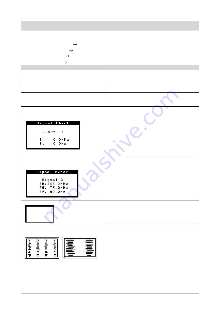
2.The error message below appears

 This message appears when no signal is input. 

(This is displayed for about 40 seconds.) 

These messages appear when the signal is not inputted 
correctly, even if the monitor functions properly.
• When the image is displayed correctly after a short time, 

there is no problem with the monitor. (Some PCs do not 
output the signal soon after powering on.)

• Check that the PC is turned ON.
• Check that the signal cable is properly connected to the PC 

or graphics board.

• Switch the signal input by touching the Input Signal Selection 

switch on the control panel.

• The signal frequency is out of range. Error signal 

frequency will be displayed in red. 
(Example) 

• Use the graphics board's utility software to change the 

frequency setting. (Refer to the manual of the graphics 
board.)

3.Display position is incorrect. 

• Adjust the image position using the <Position(page 24).

 If the problem persists, use the graphics board's utility 

software to change the display position if available.

4.Screen image is smaller or larger than the actual 

screen images.

• Adjust the resolution using the <Resolution(page 25).

5.Vertical bars of distortion appear. 

• Decrease the vertical bars using the <Clock> (page 24).

Summary of Contents for ColorEdge CE210W

Page 1: ...Contents 8 1 3 Controls Connectors 9 2 CABLE CONNECTION 11 2 1 Before Connecting 11 2 2 Connecting the Signal Cable 12 2 3 Connecting Two PCs to the Monitor 16 3 ScreenManager 18 3 1 How to use the Sc...

Page 2: ...ade pursuant to EIZO NANAO CORPORATION s receipt of said information Although every effort has been made to ensure that this manual provides up to date information please note that EIZO monitor speci...

Page 3: ...our dealer for advice Attempting to use a malfunctioning unit may result in fire electric shock or equipment damage Do not open the cabinet or modify the unit Opening the cabinet or modifying the unit...

Page 4: ...power outlet of your country Be sure to remain within the rated voltage of the power cord Not doing so may result in re or electric shock Power supply 100 120 200 240 Vac 50 60 Hz To disconnect the po...

Page 5: ...ving the unit with the cord attached is dangerous It may result in injury When handling the unit grip the bottom of the unit firmly with both hands ensuring the panel faces outward before lifting Drop...

Page 6: ...the pressed image is dark or black If pressure is repeatedly applied to the screen it may deteriorate or damage your LCD panel Leave the screen white or black to decrease the prints When the screen i...

Page 7: ...neContrast modes to select the most suitable mode for screen display The ArcSwing Stand enables to adjust the monitor height and monitor angle freely CE240W 24 wide format LCD Dual inputs compliant DV...

Page 8: ...ble FD C16 Digital Signal Cable FD C39 EIZO USB Cable MD C93 EIZO LCD Utility Disk CD ROM Calibration software ColorNavigator CE in the CD ROM ColorNavigator CE Quick Reference User s Manual in the CD...

Page 9: ...ch AUTO Adjust the screen to appropriate condition automatically analog input only 5 Enter Switch ENTER Show the ScreenManager on the screen Con rm the setting adjustment function Save the adjustment...

Page 10: ...sington s MicroSaver security system For further information please consult Kensington Technology Group 2855 Campus Drive San Mateo CA 94403 USA Tel 800 650 4242 x3348 Intl 650 572 2700 x3348 Fax 650...

Page 11: ...e Macintosh 640 480 85Hz VGA VESA 720 400 70Hz VGA TEXT 800 600 85Hz VESA 832 624 75Hz Apple Macintosh 1024 768 85Hz VESA 1152 864 75Hz VESA 1152 870 75Hz Apple Macintosh 1280 960 60Hz VESA 1280 960 7...

Page 12: ...60Hz 162 MHz Max VGA 720 400 70Hz VGA TEXT 800 600 60Hz VESA 1024 768 60Hz VESA 1280 960 60Hz VESA 1280 1024 60Hz VESA 1600 1200 60Hz VESA 1680 1050 60Hz VESA CVT VESA CVT RB Reduced Blanking 1920 12...

Page 13: ...I Digital Graphics card Power Mac G4 G5 DVI NOTE The monitor is not compatible with a Power Mac G4 G5 ADC Apple Display Connector 2 Plug the power cord into the power connector on the rear of the moni...

Page 14: ...height of the monitor To heighten push the monitor backward To lower pull the monitor forward 2 Adjust the position and angle of the monitor To adjust the angle of the monitor hold the stand with one...

Page 15: ...the right top corner of the screen Adjust brightness of the screen depending on the brightness of your environment Too dark or toobright of a screen can cause eyestrain Be sure to take adequate rests...

Page 16: ...elect either SIGNAL 1 or SIGNAL 2 as the active input at any time Every time the switch is touched the input changes When switching the signal the kind of the input signal Signal 1 or 2 Analog or Digi...

Page 17: ...h inputs are present the monitor gives preference to Signal 2 in the following cases When the power of the monitor is turned ON When the signal input to Signal 2 is changed even if active input was Si...

Page 18: ...The setting menu appears 3 Use the Directing switches to make all required adjustments and touch the Enter switch to save the settings 3 Exiting the ScreenManager 1 To return to the main menu select...

Page 19: ...er Set the menu displaying time Translucent Set the transparency of the background Power Indicator Make non light for blue lighting when the screen is displayed Power Indicator Setting Reset Return to...

Page 20: ...Mode Settings Brightness Temperature and Gamma settings can be adjusted on the FineContrast menu Select the desired function icon with the Up Down Directing switches and adjust with the Left Right Di...

Page 21: ...state after a predetermined amount of time has lapsed This function was created to reduce Afterimage characteristics that are particular to LCD monitors when the monitor screen is left on for a long...

Page 22: ...monitor the EIZO logo is displayed for a while If you desire to display or undisplay this logo use this function Default is logo appearing To undisplay 1 Turn off the monitor s power by touching the...

Page 23: ...clock phase screen position and resolution If you do not wish to do adjust the screen do not touch the Auto Adjustment switch again NOTE The Auto adjustment function is intended for use on the Macinto...

Page 24: ...creen Use the Phase adjustment Select the Phase and eliminate the horizontal ickering blurring or bars by using the Right and Leftswitches NOTE Horizontal bars may not completely disappear from the sc...

Page 25: ...ust thehorizontal resolution using the Right and Left switches 4 Adjust the output signal range Dynamic Range of the signal Use the Range Adjustment of Screen menu This controls the level of output si...

Page 26: ...cal resolution and horizontal resolution are enlarged at same rates some horizontal or vertical image maydisappear Normal Displays the picture at the actual Screen resolution CE210W Example Displaying...

Page 27: ...dvance by using the FineContrast Mode Adjustment Items The adjustable items and displayed icons on the Color menu depend on the selected FineContrast mode Settable Adjustable Fixed at the factory Icon...

Page 28: ...ustment Gamma To set the gamma value 1 8 2 6 Tips If setting the gamma value the using the monitor in the digital signal input is recommended If using the monitor in the analog input signal set the ga...

Page 29: ...r is in a power saving mode Analog Input This monitor complies with the VESA DPMS standard and adopts a power saving method Procedure 1 Set the PC s power saving settings 2 Select VESA DPMS from the P...

Page 30: ...tible PC or peripherals is recommended If the monitor is in the power saving mode or if the monitor is connected to the power outlet with the monitor turned off all the devices connected to the USB po...

Page 31: ...s USB hub is available for connecting USB compliantperipherals to the downstream ports of the monitor Connecting Examples Scanner Keyboard Mouse PC Downstream Port Connect the cables from USB complain...

Page 32: ...le Weight Total weight of the monitor without stand and attaching equipment such as a cable T V GS approved arm or stand Please connect cables after attaching an arm stand This monitor does not suppor...

Page 33: ...n the arm mounting 100 mm x 100 mm VESA compliant 200 100 100 100 100 4 Mounting Screws enclosed M4 x 12 mm Arm Stand Hole spacing on the arm mounting 200 mm x 100 mm VESA compliant 200 100 100 100 10...

Page 34: ...These messages appear when the signal is not inputted correctly even if the monitor functions properly When the image is displayed correctly after a short time there is no problem with the monitor So...

Page 35: ...htly light or dark This is due to the characteristics of the panel itself and not the LCD product 13 Fingerprints remain on the screen Leave the monitor with a white screen or a black screen The sympt...

Page 36: ...not operate Check that the USB cable is correctly connected Check the downstream ports by connecting the peripherals to other downstream ports If the problem is solved by doing this contact an EIZO de...

Page 37: ...or LCD panel Cabinet To remove stains wipe the cabinet with a soft lightly moistened cloth using a mild detergent Do not spray wax or cleaner directly into the cabinet For details refer to the manual...

Page 38: ...USB Less than 2 W for single signal inputwithout USB Input Connector DVI I 2 Analog Input Signal Sync a Separate TTL Positive Negative b Composite TTL Positive Negative Analog Input Signal Video 0 7...

Page 39: ...han 2 W for single signal inputwithout USB Input Connector DVI I 2 Analog Input Signal Sync a Separate TTL Positive Negative b Composite TTL Positive Negative Analog Input Signal Video 0 7 Vp p 75 ohm...

Page 40: ...On Language English Beeper settings Short beep ScreenManager item selected ScreenManager parameter adjusted to minimum or maximum limit Input Signal Selection Button pressed Long beep Auto Adjustment...

Page 41: ...9 SPECIFICATIONS 41 Dimensions CE210W mm inch...

Page 42: ...6 294 11 6 5 25 7 3 0 29 357 2 14 1 361 9 14 2 60 60 5 2 38 23 5 0 93 60 2 36 85 3 35 39 7 1 56 530 20 9 230 9 1 1 7 2 1 7 2 522 20 6 24 0 94 520 4 20 5 326 12 8 22 8 0 9 25 0 98 116 4 6 14 5 0 57 80...

Page 43: ...Power 24 TMDS Clock 5 NC 15 Ground return for 5V Hsync and Vsync C1 Analog Red 6 DDC Clock SCL 16 Hot Plug Detect C2 Analog Green 7 DDC Data SDA 17 TMDS Data0 C3 Analog Blue 8 Analog Vertical Sync 18...

Page 44: ...displayed through the color lter of the LCD panel Red green and blue are the three primary colors The colors on the monitor are displayed by combining these three colors The color tone can change by...

Page 45: ...omewhat blue while at lower temperatures it appears somewhat red Computer monitors generally give best performance at high temperature settings 5000 K Slightly reddish white 6500 K Warm white tone sim...

Page 46: ...ive Vertical 72 81 Negative VESA 640 480 75Hz 31 5 MHz Horizontal 37 50 Negative Vertical 75 00 Negative VESA 640 480 85Hz 36 0 MHz Horizontal 43 27 Negative Vertical 85 01 Negative VESA 800 600 56Hz...

Page 47: ...85Hz 56 3 MHz Horizontal 53 67 Positive Vertical 85 06 Positive VESA 1024 768 60Hz 65 0 MHz Horizontal 48 36 Negative Vertical 60 00 Negative VESA 1024 768 70Hz 75 0 MHz Horizontal 56 48 Negative Vert...

Page 48: ...y Energy saving mode after a certain time bene cial both for the user and environment Electrical safety Emissions Electromagnetic elds Noise emissions Ecology The products must be prepared for recycli...

Page 49: ...interference to radio communications However there is no guarantee that interference will not occur in a particular installation If this equipment does cause harmful interference to radio or televisio...

Page 50: ...tte ber dem Boden zwischen 135 150 cm betr gt d Der Standfu mu die M glichkeit zur Neigung des Bildschirmger tes besitzen max vorw rts 5 min nach hinten 5 e Der Standfu mu die M glichkeit zur Drehung...

Page 51: ...witzerland All recycling information is placed in the SWICO s website http www swico ch Recycling Information f r Kunden in der Schweiz Alle Informationen zum Thema Recycling finden Sie auf der Homepa...

Page 52: ......

Reviews: