GB
- 37 -
•
The robot lawn mower will run over the two
parallel perimeter wires (18) in the mowing
area, but the robot lawn mower will stop whe-
re single perimeter wires (18) are laid.
5.5.9 Obstacles
•
Obstacles with a height over 10 cm
(Fig. 6j)
Solid obstacles which are over 10 cm in
height, e.g. trees, walls, fences, garden furni-
ture, etc., are detected by the collision sen-
sors. If the robot lawn mower collides with an
obstacle, it will stop, reverse and turn so that
it can continue mowing in the other direction.
Soft, instable and valuable obstacles need to
be protected by a perimeter island using peri-
meter wire (18).
•
Stones and low obstacles
Stones, rocks and low obstacles of less than
10 cm in the mowing area need to be protec-
ted, because otherwise the robot lawn mower
could run over them. If not, this could result
in the robot lawn mower getting damaged or
blocked.
•
Trees (Fig. 6k)
The robot lawn mower treats trees as obsta-
cles. However, where any tree roots project
above the ground to a height of less than 10
cm, the area in which they are located needs
to be protected. This will prevent damage to
the roots and to the robot lawn mower. Make
sure that the minimum distance between the
perimeter wire (18) and the obstacle is 30 cm.
5.6 Connecting the charging station
Finish laying the complete perimeter wire (18)
before you connect it to the charging station.
Keep an extra length of 1 m of perimeter wire (18)
at each end so that you can make further adjust-
ments at a later time.
Using a wire stripper, remove a length of 10 to 15
mm of the insulation at the ends of the perimeter
wire (18) for connecting to the charging station
(19).
Pull out the power plug before you connect the
perimeter wire (18) to the charging station (19).
The perimeter wire (18) laid to the front end of the
charging station (19) must be run to the back via
the cable holders on the underside of the char-
ging station (19). Connect this perimeter wire (18)
to the “+” connection and the rear perimeter wire
to the “S1” connection. (Fig. 7a)
Important! Perimeter wires (18) must not
cross over!
Then connect the power supply. The LED indica-
tor (21) on the charging station (19) should light
up green and stay on permanently. If the LED
does not light up, check the connections
fi
rst. If
the LED lights up green but not permanently, read
the “Indicators on the charging station and trou-
bleshooting” table at the end of these operating
instructions.
5.7 Switching on and checking the
installation
As soon as the LED indicator (21) on the charging
station (19) lights up green, the mowing area is
ready for the robot lawn mower. Please check
fi
rst
that all the fastening pegs (14) on the perimeter
wire (18) have been fully tapped in. Place the ro-
bot lawn mower about 3 m to the rear of the char-
ging station (19) in front of the perimeter wire (18).
The robot lawn mower needs to be facing the
perimeter wire (18) at an angle of 90° (Fig. 7b).
Switch on the main switch (7) (ON) (Fig. 8).
Press the POWER button (60) on the control
panel (2) for two seconds. Unlock the robot lawn
mower using the PIN and con
fi
rm the entry with
the “OK” button (61) (see chapter “Locking me-
chanism / PIN”).
Press the “HOME / 3” button (64) and then press
the “OK” button again (61). The robot lawn mower
will now follow the perimeter wire (18) in a coun-
terclockwise direction. Observe the robot lawn
mower during the complete trip along the perime-
ter wire (18) until it is back in the charging station
(19). If the robot lawn mower has any problems
at any points, correct the perimeter wire (18) if
necessary and repeat the operation. The rechar-
geable battery (22) of the robot lawn mower will
now be fully charged. If any problems occur with
docking, you may need to reposition the charging
station (19) sideways until docking works without
any problems.
To stop the robot lawn mower at any time, press
the red STOP button (3). When you press the
STOP button (3), the robot lawn mower will come
to a stop and wait for further instructions.
5.8 Securing the charging station
Once the robot lawn mower operates properly
and a suitable position for the charging station
(19) has been found, the charging station (19)
must be secured using the fastening nails (15).
Using a hammer, tap the fastening nails (15) com-
pletely into the ground. (Fig. 7c)
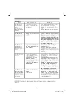
Anl_FREELEXO_Kit_600_SPK9.indb 37
Anl_FREELEXO_Kit_600_SPK9.indb 37
14.11.2019 12:34:59
14.11.2019 12:34:59


