background image

6

Safety Instructions

Openings in the cabinet are provided for ventilation. To 

ensure reliable operation of the product and to protect it 

from  overheating,  these  openings  must  not  be  blocked 

or covered. 


CAUTION

Hot air is exhausted from the exhaust vent. When using 
or  installing  the  projector,  the  following  precautions 
should be taken. 
– Do not put any flammable object or spray can near the 

projector, hot air is exhausted from the air vents.

– Keep the exhaust vent at least 3’ (1 m) away from any 

objects.

–  Do  not  touch  a  peripheral  part  of  the  exhaust  vent, 

especially screws and metallic parts. These areas will 
become hot while the projector is being used.

–  Do not put anything on the cabinet. Objects put on the 

cabinet will not only get damaged but also may cause 
fire hazard by heat.

Cooling  fans  are  provided  to  cool  down  the  projector. 
The  fans’  running  speed  is  changed  according  to  the 
temperature inside the projector.


CAUTION

The carrying case (supplied) is intended for protection
against dust and scratches on surface of the cabinet,
and it is not designed to protect an appliance from
external forces. Do not transport the projector by courier
or any other transport service with this case, otherwise
the projector can be damaged. When handling the
projector, do not drop, bump, subject it to strong forces,
or put other things on the cabinet.

Moving the Projector

When moving the projector, replace the lens cap and 
retract adjustable feet to prevent damage to the lens and 
cabinet.
When the projector is not in use for an extended period, 
put it into the supplied carrying case with the lens side 
up.

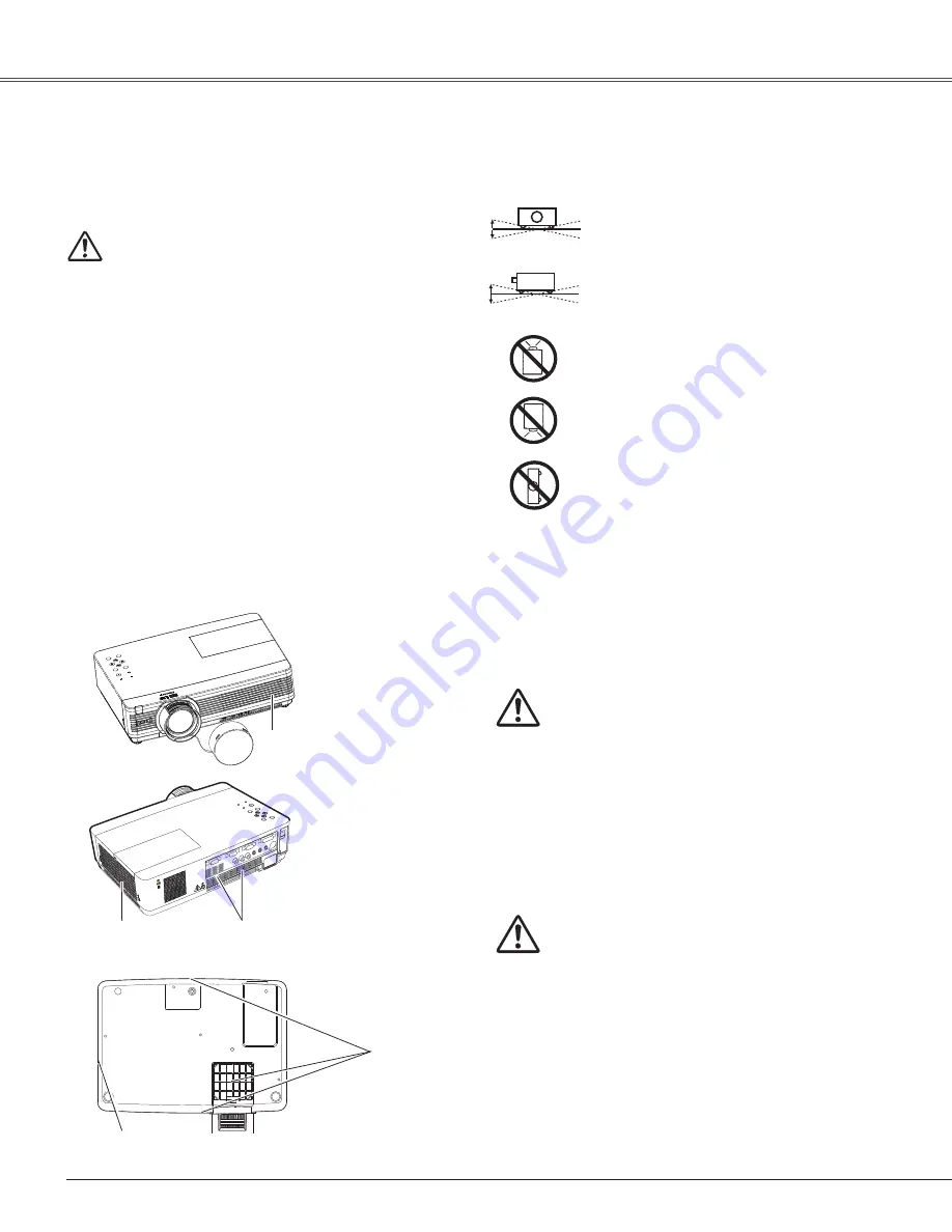
Air Circulation

Air Intake Vent

Exhaust Vent
(Hot air exhaust)

Air Intake Vent

Do not tilt the projector more than 30 

degrees from above and below.

Do not point the projector up to project an 

image.

Do not point the projector down to project 

an image. 

Do not put the projector on either side to 

project an image. 

Install  the  projector  properly.  Improper  Installation  may 

reduce the lamp life and cause a fire hazard.

Installing the Projector in Proper Position

Do not tilt the projector more than 20 

degrees from side to side.

20°

20°

30°

30°

Air Intake Vent

Exhaust Vent
(Hot air exhaust)


CAUTION IN CARRyING OR TRANSPORTING   


THE PROjECTOR

– Do not drop or bump the projector, otherwise damages 

or malfunctions may result.

– When carrying the projector, use a suitable carrying case.
– Do not transport the projector by courier or any other 

transport service in an unsuitable transport case. This 
may cause damage to the projector. For information 
about transporting the projector by courier or any other   
transport service, consult your dealer.

– Do not put the projector in a case before the projector is 

cooled enough.

Summary of Contents for LC-XB100A

Page 1: ...work Supported Wired LAN Refer to the Owner s Manuals below for details about network function Network Set up and Operation PJ Network Manager Multimedia Projector Owner s Manual LC XB100A LC XB200A MODEL ...

Page 2: ...h Portuguese Dutch Swedish Finnish Polish Hungarian Romanian Russian Chinese Korean Japanese and Thai p 46 Note The On Screen Menu and figures in this manual may differ slightly from the product The contents of this manual are subject to change without notice Security Function The Security function helps you to ensure security of the projector With the Key lock function you can lock the operation ...

Page 3: ...23 Menu Bar 24 Zoom and Focus Adjustment 25 Auto Setup Function 25 Keystone Correction 25 Sound Adjustment 26 Remote Control Operation 27 Computer Input 29 Input Source Selection RGB Computer 1 Computer 2 Analog 29 Input Source Selection RGB PC digital RGB AV HDCP 30 Computer System Selection 31 Auto PC Adjustment 32 Manual PC Adjustment 33 Image Mode Selection 35 Image Adjustment 36 Screen Size A...

Page 4: ...e directly into the beam Install the projector in a proper position Otherwise it may result in fire hazard Allowing the proper amount of space on the top sides and rear of the projector cabinet is critical for proper air circulation and cooling of the unit The dimension shown here indicate the minimum space required If the projector is to be built into a compartment or similarly enclosed these min...

Page 5: ...e points or short out parts that could result in a fire or electric shock Never spill liquid of any kind on the projector Do not install the projector near the ventilation duct of air conditioning equipment This projector should be operated only from the type of power source indicated on the marking label If you are not sure of the type of power supplied consult your authorized dealer or local pow...

Page 6: ...e projector do not drop bump subject it to strong forces or put other things on the cabinet Moving the Projector When moving the projector replace the lens cap and retract adjustable feet to prevent damage to the lens and cabinet When the projector is not in use for an extended period put it into the supplied carrying case with the lens side up Air Circulation Air Intake Vent Exhaust Vent Hot air ...

Page 7: ...ters Laboratories UL and certified by the Canadian Standard Association CSA AC Power Cord has a grounding type AC line plug This is a safety feature to be sure that the plug will fit into the power outlet Do not try to defeat this safety feature Should you be unable to insert the plug into the outlet contact your electrician GROUND AC Power Cord Requirement AC Power Cord for the United Kingdom Thi...

Page 8: ...Controls and Indicators LAN Connection Terminal Power Cord Connector Filters Adjustable Feet Note LAN Connection Terminal is for the Network function Refer to the owner s manual of Network Set up and Operation Kensington Security Slot This slot is for a Kensington lock used to deter theft of the projector Kensington is a registered trademark of ACCO Brands Corporation CAUTION Do not turn on a proj...

Page 9: ...mputer RGB scart 21 pin video output or component video output to this terminal pp 16 18 AUDIO OUT VARIABLE Connect an external audio amplifier to this jack pp 16 18 This terminal outputs sound from AUDIO IN terminal or MONITOR OUT This terminal can be used to output the incoming analog RGB signal and component signal from COMPUTER IN 2 DVI I terminal or COMPUTER IN 1 COMPONENT IN terminal to the ...

Page 10: ...nd by mode Lights green during operations Blinks green in the Power management mode pp 53 72 INPUT button Select an input source pp 29 30 39 40 MENU button Open or close the On Screen Menu p 23 POINT ed 7 8 VOLUME buttons Select an item or adjust the value in the On Screen Menu p 23 Pan the image in the Digital zoom mode p 38 Adjust the volume level Point 7 8 buttons p 26 AUTO SETUP button Execute...

Page 11: ...nt ed 7 8 VOLUME buttons Select an item or adjust the value in the On Screen Menu p 23 Pan the image in the Digital zoom mode p 38 Adjust the volume level Point 7 8 buttons p 26 NO SHOW button Temporarily turn off the image on the screen p 28 LASER button Operate the Laser pointer function Laser beam is emitted while pressing this button within 1 minute When using this laser pointer for more than ...

Page 12: ...mote control 30 Press the lid downward and slide it Two AAA size batteries For correct polarity and be sure battery terminals are in contact with pins in compartment Part Names and Functions While pressing the MENU button press the IMAGE button number of times corresponding to the remote control code MENU button IMAGE button RESET ON ALL OFF switch Remote Control Code Remote Control Code Number of...

Page 13: ...e Pointer function 1 Press the LASER button on the remote control pointing toward the projector The Spotlight or Pointer is displayed on the screen with the LASER button lighting green Then move the Spotlight or Pointer with the PRESENTATION POINTER button If the LASER button does not light green and continues to emit a laser beam try the abovementioned procedure until the LASER button lights gree...

Page 14: ...with the VGA cable Connect the USB Infrared Receiver to the USB port of your computer PRESENTATION POINTER button R CLICK button L CLICK button Wireless Mouse Operation The remote control can be used as a wireless mouse for your computer Act as left click mouse button Move the pointer on the screen with this button Act as right click mouse button Before operating the wireless mouse connect the USB...

Page 15: ...83m 15 8 4 81m 23 7 7 23m 2 3 0 69m 7 8 2 39m 11 8 3 6m 15 8 4 81m 23 7 7 23m A B 30 62 93 124 186 2 3 0 69m 3 7 1 14m 30 Adjustable Feet Adjustable Feet Feet Lock Latches Projection angle can be adjusted up to 12 0 degrees with the adjustable feet Lift the front of the projector and press the feet lock latches on both side of the projector Release the feet lock latches to lock the adjustable feet...

Page 16: ...AUDIO IN terminals when using the COMPUTER IN 1 COMPONENT IN and the COMPUTER IN 2 DVI Iterminals as input When the AUDIO OUT is plugged in the projector s built in speaker is not available When input RGB PC digital source to the MONITOR OUT terminal the MONITOR OUT terminal is not available External Audio Equipment Audio cable stereo Audio cable stereo Monitor Input Audio Output COMPUTER 1 COMPUT...

Page 17: ...lug the power cords of both the projector and external equipment from the AC outlet before connecting cables Note When the AUDIO OUT is plugged in the projector s built in speaker is not available External Audio Equipment Audio cable stereo VIDEO S VIDEO S Video cable Video and audio cable Video and Audio Output S Video Output AUDIO IN Audio Input AUDIO OUT stereo R L Video ...

Page 18: ...before connecting cables Cables used for connection Audio Cables Scart VGA Cable VGA Cable Component Cable Component VGA Cable Cables are not supplied with this projector External Audio Equipment COMPUTER 1 AUDIO IN Audio cable stereo Audio cable stereo Audio Input Component Video Output Y Pb Cb Pr Cr RGB Scart 21 pin Output Audio Output Scart VGA cable Component VGA cable AUDIO OUT stereo Compone...

Page 19: ...e projector is not in use When this projector is connected to an outlet with the AC power cord it is in Stand by mode and consumes a little electric power To the AC outlet 200 240 V AC NOTE ON THE POWER CORD AC power cord must meet requirement of the country where you use the projector Confirm the AC plug type with the chart below and proper AC power cord must be used If supplied AC power cord doe...

Page 20: ... in the Display function the countdown will not be shown on the screen p 48 When the Input Search function is set to On2 the input signal will be searched automatically p 47 When Off is selected in the Display function the Video PC selection window and the input signal guidance window are not shown on the screen p 48 5 If there is no signal input when start on the projector or the current signal i...

Page 21: ... complete entering a four digit number After entering the four digit number move the pointer to Set Press the SELECT button so that you can start to operate the projector If you entered an incorrect PIN code PIN code and the number will turn red for a moment Enter the correct PIN code all over again CAUTION ON HANDLING PIN CODE If you forget your PIN code the projector can no longer be started Tak...

Page 22: ... outlet p 53 The running speed of cooling fans is changed according to the temperature inside the projector Do not put the projector in a case before the projector is cooled enough If the WARNING indicator blinks or lights red see WARNING indicator on page 61 While the POWER indicator is blinking the lamp is being cooled down and the projector cannot be turned on Wait until the POWER indicator sto...

Page 23: ...Point ed buttons to select the desired submenu item and press the SELECT button to set or access the selected item Press the MENU button on the top control or the remote control to display the On Screen Menu 1 2 3 On Screen Menu Top Control MENU button SELECT button POINT buttons arrowhead Point 8 or SELECT button Use the Point ed7 8 buttons to adjust the setting or switch between each option and ...

Page 24: ...sive pp 43 44 PC adjust Select Auto PC adj Fine sync Total dots Horizontal Vertical Clamp Display area H and Display area V to adjust the parameters to match with the PC input signal format p 32 34 Screen For computer source used to adjust size of the image Normal True Wide Full Custom and Digital zoom pp 36 37 For Video source used to set size of image Normal Wide and Custom p 45 Input Used to se...

Page 25: ...on Auto setup function is provided to automatically execute the setting of Auto setup includes Input search Auto PC adj and Auto Keystone functions in the setting menu by just pressing the AUTO SETUP button on the top control or the AUTO SET button on the remote control Refer to page 47 for the setting of the Auto setup function Notes Auto Keystone corrects vertical distortion only it does not cor...

Page 26: ...e function is also effective for the AUDIO OUT jack Press the SELECT button to switch the mute function On Off When the sound is turned off On is displayed Press the VOLUME buttons again to turn the sound back on Use the Point ed buttons to select the desired submenu item and press the SELECT button to access the selected item Volume Volume Mute Press the Point e button to turn up the volume press...

Page 27: ...pear on the Screen menu while the Freeze function is working FREEZE button Display the input source information Input H sync freq V sync freq Screen Language Lamp status Lamp counter Power management Keylock PIN code lock and Remote control p 60 INFO button Press the D ZOOM buttons on the remote control to enter to the Digital zoom mode See page 38 for details D ZOOM buttons Note See the next page...

Page 28: ...appears on the screen and the countdown starts 00 00 59 59 To stop the countdown press the P TIMER button To cancel the P Timer function press the P TIMER button again P TIMER button Press the IMAGE button on the remote control to select a desired image mode of the screen See pages 35 42 for details IMAGE button No show disappears after 4 seconds P Timer display Note See the previous page for the ...

Page 29: ...een Menu Use the Point ed buttons to select Input and then press the Point 8 or the SELECT button RGB PC digital NTSC RGB PC digital INPUT button Input Source Selection RGB Computer 1 Computer 2 Analog Video Computer 2 PC digital AV HDCP Analog S video Computer 1 RGB Component Scart COMPUTER button Remote Control Use the Point ed buttons to select either Computer 1 or Computer 2 and then press the...

Page 30: ... from being copied The specification of HDCP is decided and controlled by Digital Content Protection LLC Should the specification be changed this projector may not display the digital content protected by HDCP Top Control 1 2 Press the MENU button to display the On Screen Menu Use the Point ed buttons to select Input and then press the Point 8 or the SELECT button Use the Point ed buttons to selec...

Page 31: ... from the computer Check the connection between your computer and the projector See Troubleshooting on p 67 Auto The preset system is manually adjusted in the PC adjust Menu The adjusted data can be stored in Mode 1 5 pp 33 34 Mode 1 PC Systems provided in this projector is chosen The projector chooses a proper system provided in the projector and displays it SVGA 1 Mode 1 and SVGA 1 are examples ...

Page 32: ...l position of some computers cannot be fully adjusted with the Auto PC Adjustment function When the image is not provided properly with this operation manual adjustments are required pp 33 34 The Auto PC Adjustment cannot be operated when 480i 575i 480p 575p 720p 1035i or 1080i is selected in the PC System Menu p 31 Press the MENU button to display the On Screen Menu Use the Point ed buttons to se...

Page 33: ...eriod to match your PC image Total dots Use the Point 7 8 buttons to adjust the horizontal picture position Horizontal Use the Point 7 8 buttons to adjust the vertical picture position Vertical Use the Point 7 8 buttons to adjust the clamp level When the image has dark bars try this adjustment Clamp Press the MENU button to display the On Screen Menu Use the Point ed buttons to select PC adjust an...

Page 34: ...75i 480p 575p 720p 1035i or 1080i is selected in the PC System Menu p 31 PC adjust Menu cannot be selected when Computer 2 PC digital and Computer 2 AV HDCP are selected in the Input Menu p 30 When input computer signal to the projector PC adjust will become available Reset To reset the adjusted data select Reset and press the SELECT button A confirmation box appears and then select Yes All adjust...

Page 35: ...lack colored board Dynamic Direct Operation For viewing pictures in a bright room Normal picture mode preset on the projector For viewing with the user preset image mode in the Image Adjust Menu see pages 36 37 This Image memory is provided in each computer component S video and video input source 1 2 Menu Operation Colorboard Colorboard At the time of simple projection on the colored wall you can...

Page 36: ...from 0 to 63 Contrast Brightness Press the Point 7 button to lighten red tone press the Point 8 button to deepen red tone from 0 to 63 White balance Red Press the Point 7 button to lighten green tone press the Point 8 button to deepen green tone from 0 to 63 White balance Green Press the Point 7 button to lighten blue tone press the Point 8 button to deepen blue tone from 0 to 63 White balance Blu...

Page 37: ...han it reset the resolution to the lower before connecting to the projector The image data in other than 1024 x 768 is modified to fit the screen size in initial mode True Full and Digital zoom cannot be selected when 480i 575i 480p or 575p is selected in the PC System Menu p 31 1 2 To store the adjusted data select Store and press the Point 8 or the SELECT button Use the Point ed buttons to selec...

Page 38: ...elected for the screen size True Full and Digital zoom cannot be selected when 480i 575i 480p or 575p is selected in the PC System Menu p 31 Digital zoom cannot be selected when Full or True is selected When Custom is selected the Digital zoom function is disabled Adjust the screen scale and position manually with this function Press the Point 8 button at Custom and the Custom is displayed on the ...

Page 39: ...eo input signal is connected to the S VIDEO jack select S video S video Note When the Input Search function is set to On1 or On2 in the Auto setup function the input signal will be searched automatically p 47 Top Control INPUT button Press the MENU button to display the On Screen Menu Use the Point ed buttons to select Input and then press the Point 8 or the SELECT button Use the Point ed buttons ...

Page 40: ...nent When the input source is coming from video equipment connected to the COMPUTER IN 1 COMPONENT IN terminal with a Scart VGA Cable select RGB Scart RGB Scart Direct Operation Menu Operation Press the MENU button to display the On Screen Menu Use the Point ed buttons to select Input and then press the Point 8 or the SELECT button Note When the Input Search function is set to On1 or On2 the input...

Page 41: ...PONENT VIDEO SIGNAL FORMAT Video or S video Component The projector automatically detects an incoming video system and adjusts itself to optimize its performance When Video System is PAL M or PAL N select the system manually Auto Note The AV System Menu cannot be selected when selecting RGB Scart Press the MENU button to display the On Screen Menu Use the Point ed buttons to select Input and then ...

Page 42: ... pictures in a bright room Normal picture mode preset on the projector For viewing with the user preset image mode in the Image Adjust Menu see pages 43 44 This Image memory is provided in each computer scart component S video and video input source 1 2 Menu Operation Image 1 Image 2 Image 3 Image 4 Colorboard Colorboard At the time of simple projection on the colored wall you can get the close co...

Page 43: ... Point 7 button decrease the intensity of the color press the Point 8 button increase the intensity of the color from 0 to 63 Press the Point 7 8 buttons to adjust the tint value to get a proper color balance from 0 to 63 Color Tint Note When the White balance Red Green or Blue is adjusted the Color temp level will change to User Tint cannot be selected when the video system is PAL SECAM PAL M or ...

Page 44: ...ce on the screen can be reduced Select one of the following options to get smoother images Off Disabled L1 Lower reduction L2 Higher reduction Note Noise reduction and Progressive cannot be selected when 480p 575p 720p 1035i or 1080i is selected p 41 To reset the adjusted data select Reset and press the SELECT button A confirmation box appears and then select Yes All adjustments will return to the...

Page 45: ... Common Save the adjusted scale or position to all the inputs Press the SELECT button at Common to display a confirmation box To save the scale or position press the SELECT button at Yes When Custom is selected the saved scale or position is used Reset Reset the all adjusted values Press the SELECT button at Reset to display a confirmation box To reset press the SELECT button at Yes Note When no s...

Page 46: ...ct the desired item and then press the Point 8 or the SELECT button to access the selected item This projector has a Setting menu that allows you to set up the other various functions described below Language Menu position This function is used to change the position of the On Screen Menu Select Menu position and press the SELECT button The Menu position screen appears The Menu position changes ea...

Page 47: ...l When pressing the AUTO SETUP button on the top control When the current input signal is cut off If the No show or Freeze function is active cancel it to activate the Input search It is also unavailable when On Screen menu is displayed Auto PC adj On Enables Auto PC Adjustment when pressing the AUTO SET button on the remote control or the AUTO SETUP button on the top control Off Disables Auto PC ...

Page 48: ... blue background User Project an image selected in the Logo setting Black Project a black background This function decides whether to display On Screen Displays On Show all the On Screen displays Use this function when you want to project images after the lamp becomes bright enough The factory default setting is in this option Countdown Off Show the input image instead of the countdown when turnin...

Page 49: ... and Logo PIN code change functions Note When On is selected in the Logo PIN code lock function Logo select and Capture functions cannot be selected Logo select Off Off Closed caption This function decides on the starting up display from among following options Off Show the countdown display only Default Show the factory set logo User Show the image you captured ...

Page 50: ...image that has been adjusted by the Keystone function the adjusted data is automatically reset and the projector captures an image without keystone correction When Logo PIN code lock is set to On capture cannot be selected When starting to capture a new image the previously stored image is cleared even if you cancel the capturing When there is no captured image or it is interrupted while capturing...

Page 51: ...ress the SELECT button to select Logo PIN code change Logo PIN code dialog box appears use the Point ed buttons to enter the correct code The New Logo PIN code input dialog box appears Set a new Logo PIN code confirmation box appears choose Yes to set the new Logo PIN code Be sure to note the new Logo PIN code and keep it on hand If you lost the number you could no longer change the Logo PIN code ...

Page 52: ...ontains closed captions you can turn on the feature and switch the channels Press the Point ed buttons to select Off CC1 CC2 CC3 or CC4 If the closed caption is not clear you can change the text from Color to White Note The Closed Caption is available only under the situation below When the input signal is NTSC of composite and S video and the system is set according to the signal or set on Auto T...

Page 53: ...is pressed Shut down When the lamp has been fully cooled down the power will be turned off Off Power management function is off Timer If the input signal is interrupted and no button is pressed for more than 30 seconds the timer display with No signal appears It starts the countdown until the lamp is turned off Use the Point ed buttons to set the Timer 1 30min Note Factory default is Ready 5 min O...

Page 54: ...ours of use the replacement icon will be displayed at the time of power on Then the projector will turn off after 3 minutes The Lamp replacement icon will not appear when the Display function is set to Off p 48 during Freeze p 27 or No show p 28 Lamp replacement icon Standby mode This function is available when operating the projector via network Network Supply the power to the network function ev...

Page 55: ... 8 The same code should set on both the projector and the remote control For example operating the projector in Code 7 the remote control code also must be switched to Code 7 To change the code for the projector Select a remote control code in this Setting Menu To change the code for the remote control While holding down the MENU button press the IMAGE button the number of times corresponding to t...

Page 56: ...tion allows you to use the Key lock and PIN code lock function to set the security for the projector operation This function prevents the projector from being operated by unauthorized persons and provides the following setting options for security Off Unlocked On1 Enter the PIN code every time turning on the projector On2 Enter the PIN code to operate the projector once the power cord is disconnec...

Page 57: ...ber move the pointer to Set Press the SELECT button so that you can change the following PIN Code lock setting If you entered an incorrect PIN code PIN code and the number will turn red for a moment Enter the correct PIN code all over again Enter a PIN code Change the PIN code Change the PIN code caution when you have changed THE PIn code write down the new pin code in column of the pin code no me...

Page 58: ...er altitudes than above where the fans have lesser cooling effect Note The fan noise becomes louder in On 1 and On2 Fan control This function is used to set a frequency for the filter cleaning When the projector reached a specified time between cleanings a Filter warning icon appears on the screen notifying the cleaning is necessary After cleaning the filter be sure to select Reset and set the tim...

Page 59: ...actory default Warning log This function records anomalous operations while the projector is in operation and use it when diagnosing faults Up to 10 warning logs are displayed with the latest warning message at the top of the list followed by previous warning messages in chronological order Note When the Factory default function is executed all the warning log records will be deleted Yes No ...

Page 60: ...layed Direct Operation Press the INFO button on the remote control to display the Information Menu Remote Control Press the Point ed buttons to select the Information The Information Menu is displayed See below for displayed information Menu Operation Power management Screen Off Ready Shut down or Timer is displayed The selected screen size is displayed Input Lamp status The selected input source ...

Page 61: ... this case unplug the AC power cord and reconnect it and then turn the projector on once again to verify operation If the projector cannot be turned on and the WARNING indicator still lights red unplug the AC power cord and contact the service station CAUTION DO NOT LEAVE THE PROJECTOR WITH THE AC POWER CORD CONNECTED UNDER AN ABNORMAL CONDITION IT MAY RESULT IN FIRE OR ELECTRIC SHOCK Maintenance ...

Page 62: ... the projector Usage in these environments may cause poor image quality When using the projector under dusty or smoky conditions dust may accumulate on a lens LCD panels or optical elements inside the projector degrading the quality of a projected image When the symptoms above are noticed contact your authorized dealer or service station for proper cleaning Note When reinserting this filter be sur...

Page 63: ...loth When the cabinet is heavily soiled use a small amount of mild detergent and finish with a soft dry cleaning cloth Avoid using an excessive amount of cleaner Abrasive cleaners solvents or other harsh chemicals might scratch the surface of the cabinet When the projector is not in use put the projector in an appropriate carrying case to protect it from dust and scratches When moving this project...

Page 64: ...lamp cover and secure the screw 4 Loosen the screw and open the lamp cover 2 Connect the AC power cord to the projector and turn on the projector 5 Lamp Replacement CAUTION Top Control LAMP REPLACE indicator Lamp Screw Handles Screw Lamp Cover Screw Screw CAUTION When replacing the lamp because it has stopped illuminating there is a possibility that the lamp may be broken If replacing the lamp of ...

Page 65: ...the environment or conditions in which the projector and lamp are being used IF A LAMP EXPLODES THE FOLLOWING SAFETY PRECAUTIONS SHOULD BE TAKEN If a lamp explodes disconnect the projector s AC plug from the AC outlet immediately Contact an authorized service station for a checkup of the unit and replacement of the lamp Additionally check carefully to ensure that there are no broken shards or piec...

Page 66: ...ode icon appears pages 58 or 64 Image is out of focus Adjust focus of the projector See page 25 Provide proper distance between the projector and the projection screen See page 15 Check the projection lens to see if it needs cleaning See page 63 Moving the projector from a cool to warm place may result in moisture condensation on the projection lens In such cases leave the projector off and wait u...

Page 67: ... image is projected The color is strange Check the Input signal color system video system or computer system mode Make sure the Blackboard is not selected on Image select menu See pages 35 42 Some displays are not seen Check the Display function See page 48 during the operation Auto PC adjustment function Check the Input signal Auto PC adjustment function can not work does not work when 480p 575p ...

Page 68: ...age 56 Check RESET ON ALL OFF switch on the remote control is set to ON See page 13 Indicator blinks or lights Check the status of the projector with referring to Indicators and projector Condition See page 72 Wireless Mouse function does not Make sure the USB infrared receiver is connected to the USB port of work your computer See page 14 Check the mouse setting on your computer Make sure the mou...

Page 69: ...r the service center Specify the model number and explain about the problem We will advise you how to obtain service This symbol on the nameplate means the product is Listed by Underwriters Laboratories I n c I t i s d e s i g n e d a n d manufactured to meet rigid U L safety standards against risk of fire casualty and electrical hazards The CE Mark is a Directive conformity mark of the European C...

Page 70: ... 3 Image 4 Screen Yes No Systems displayed in the System Menu vary depending on an input signal Reset Yes No Sharpness 0 15 Computer Input Video Input Sound Volume Mute On Off Sound 0 63 Standard Mode 3 Mode 4 Mode 5 Clamp Digital zoom Green Blue 0 63 0 63 Store Mode free System 1 Image 4 Mode 1 Mode 2 Custom Scale H V Position Common Reset H V H V Yes No Yes No Wide On Off Input Video RGB RGB Sca...

Page 71: ...ise reduction Store Reset L1 L2 0 63 0 63 Image 2 Image 3 Image 4 L2 L1 Capture Yes No Off On Logo PIN code change Logo PIN code lock Off Projector Remote control Key lock Off On1 On2 PIN code change Film On Off Standby mode Eco Network Color temp Auto PC adj Auto keystone Auto Manual Off Offl On1 On2 Fan control Warning log H Filter counter Yes No Off 100H 200H 300H Yes No Factory default Wide Sc...

Page 72: ...s abnormally high The projector cannot be turned on When the projector is cooled down enough and the temperature returns to normal the POWER indicator stops blinking and the projector can be turned on The WARNING indicator keeps blinking The projector detects an abnormal condition and cannot be turned on Unplug the AC power cord and plug it again to turn on the projector If the projector is turned...

Page 73: ... 75 025 XGA 5 1024 x 768 60 31 74 92 VGA 7 640 x 480 43 269 85 00 575i 768 x 576 15 625 50 00 Interlace 480i 640 x 480 15 734 60 00 Interlace SXGA 12 1152 x 900 71 40 75 60 SXGA 11 1152 x 900 61 20 65 20 SVGA 10 800 x 600 32 70 51 09 SXGA 13 1280 x 1024 50 00 86 00 Interlace SXGA 2 1280 x 1024 62 50 58 60 SXGA 3 1280 x 1024 63 90 60 00 XGA 2 1024 x 768 68 677 84 997 XGA 3 1024 x 768 60 023 75 03 S...

Page 74: ...24 31 65 29 80 D 575p 768 x 575 31 25 50 00 D SVGA 800 x 600 37 879 60 32 D XGA 1024 x 768 43 363 60 00 D SXGA1 1280 x 1024 63 98 60 02 D WXGA 1 1366 x 768 48 36 60 00 D WXGA 2 1360 x 768 47 7 60 00 D WXGA 3 1376 x 768 48 36 60 00 D WXGA 4 1360 x 768 56 160 72 000 D WXGA 6 1280 x 768 47 776 59 870 D WXGA 7 1280 x 768 60 289 74 893 D WXGA 9 1280 x 800 49 572 59 870 D WXGA 10 1280 x 800 41 200 50 00...

Page 75: ...n Lamp 225 W Interface Video Input Jack RCA Type x 1 S video Input Jack Mini DIN 4 pin x 1 Audio Input Jacks RCA Type x 2 Computer 1 Computer2 Audio Input Jacks Mini Jack x 2 Computer In 1 Component Input Terminal Mini D sub 15 pin x 1 Computer In 2 DVI I Input DVI I Terminal x 1 Monitor Output Terminal Mini D sub 15 pin x 1 Control port D sub 9 pin x 1 Audio Output Jack Mini Jack stereo x 1 varia...

Page 76: ...ick Reference Guide Safety Manual AC Power Cord Remote Control and Batteries VGA Cable Lens Cap with String PIN Code Label Network Application CD ROM Soft Carrying Case USB Infrared Receiver The specifications are subject to change without notice LCD panels are manufactured to the highest possible standards Even though 99 99 of the pixels are effective a tiny fraction of the pixels 0 01 or less ma...

Page 77: ...th PJLink Standard Class 1 For PJ Link password see the owner s manual of Network Set up and Operation PJLink is a registered trademark of JBMIA and pending trademark in some countries PJ Link Notice Projector Input RGB Computer 2 Analog RGB AV HDCP RGB PC digital Component RGB Scart PJLink Input RGB 2 RGB 1 DIGITAL 2 DIGITAL 1 RGB 3 RGB 4 Video S video VIDEO 2 VIDEO 3 Computer 2 Digital Computer ...

Page 78: ...1 5 6 7 8 1 LAN TERMINAL COMPUTER 2 DVI I TERMINAL DIGITAL ANALOG 1 9 17 2 10 18 3 11 19 4 12 20 5 13 21 6 14 22 7 15 23 8 16 24 C1 C2 C3 C5 C4 T M D S Data2 No Connect T M D S Data2 No Connect T M D S Data2 Shield DDC Clock DDC Data Analog Vert sync 1 5 2 4 3 6 7 8 T M D S Data1 No Connect T M D S Data1 No Connect T M D S Data1 Shield 5V Power Ground for 5V Hot Plug Detect 9 13 10 12 11 14 15 16 ...

Page 79: ...the service station PIN Code Number Memo Factory default set No 1 2 3 4 Factory default set No 4 3 2 1 Put the label below supplied on in a prominent place of the projector s body while it is locked with a PIN code While the projector is locked with the PIN code PIN Code Lock No Logo PIN Code Lock No Should the four digit number be changed the factory set number will be invalid ...

Page 80: ...rew Holes for Ceiling Mount Screw M4 Depth 12 0 0 472 93 5 3 68 232 5 9 15 121 9 4 80 109 7 4 32 143 3 5 64 9 5 0 37 101 3 98 107 6 4 24 219 4 8 64 23 0 91 55 2 17 25 0 98 51 9 2 05 80 5 3 17 12 MAX º 3 8 0 15 42 3 1 67 24 8 0 98 40 8 1 61 ...

Page 81: ...KI CANADA Eiki International Inc P O Box 156 310 First St Unit 2 Midland ON L4R 4K8 Canada Tel 800 563 3454 705 527 4084 Fax 800 567 4069 705 527 4087 E Mail canada eiki com Eastern Europe EIKI CZECH SPOL s r o Nad Cementárnou 1163 4a Praha 4 Podolí 147 00 Czech Republic Tel 420 241 410 928 420 241 403 095 Fax 420 241 409 435 E Mail info eiki cz South East Asia EIKI Industrial M Sdn Bhd No 3A 2C 4...

Reviews: