background image


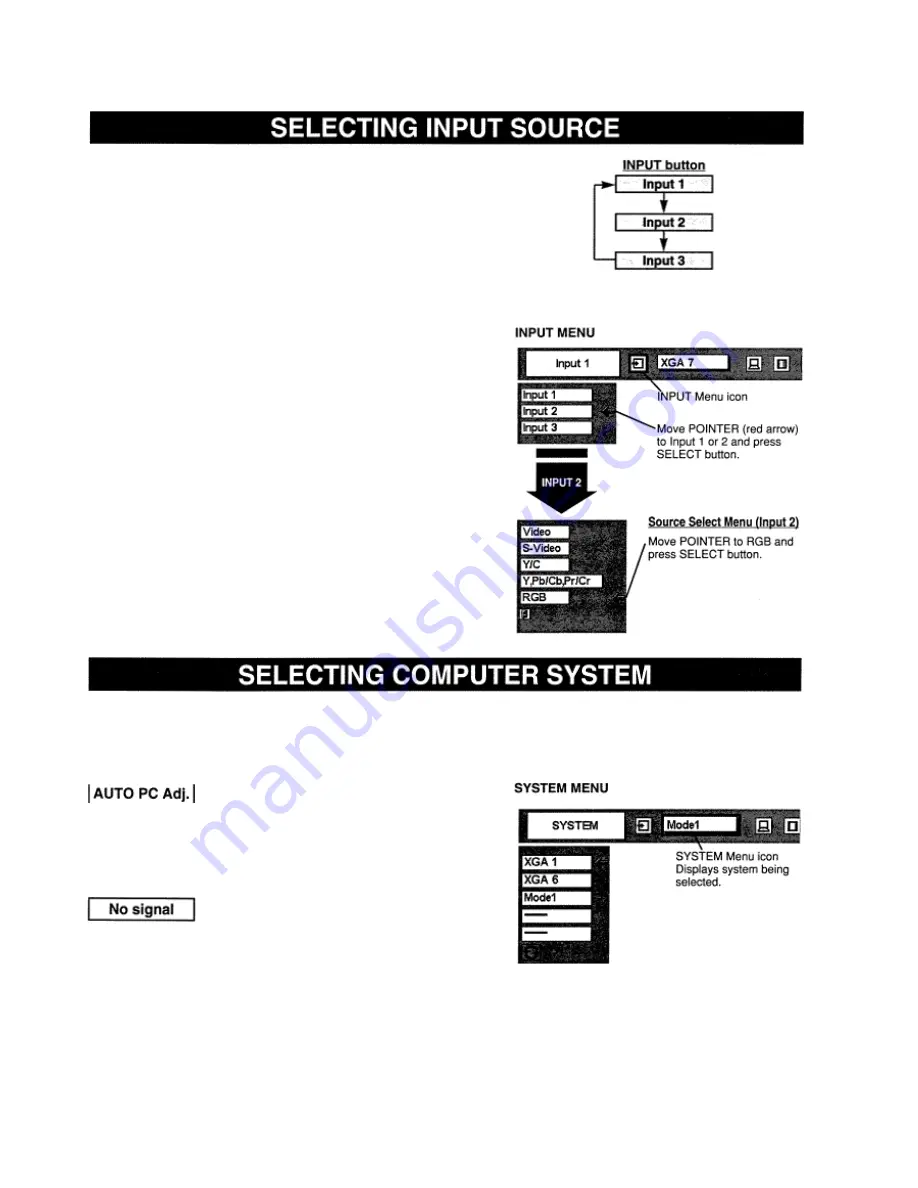
Choose either Input 1 or Input 2 by pressing INPUT button on Top 

Control or on Remote Control Unit. 


MENU OPERATION 

Press MENU button and 

ON-SCREEN MENU will appear. Press 

POINT LEFT/RIGHT button to move a red frame pointer to 
INPUT Menu icon. 


Press POINT DOWN button to move a red arrow pointer to either Input 1 or 
Input 2 that you want to choose and then press SELECT button. When 
choosing Input 2, Source Select Menu will appear. Move POINTER to RGB 
and then press SELECT button. (Input 2 accepts R, G, B, HN and V 
computer signals (P 13).) 


This projector automatically tunes to most different types of computers based on 
VGA, SVGA, XGA or SXGA (refer to 

“COMPATIBLE COMPUTER 

SPECIFICATION” on page 

27). When selecting Computer, this projector 

automatically tunes to incoming signal and projects proper image without any 
special setting. (Some computers need setting manually.) 
Note:  Proiector may display one of the foIIowin~ messanes. 


When projector cannot recognize connected signal as 
PC system provided 

in 

this projector, Auto PC Adjustment 

function operates to adjust projector 

and the message “AUTO PC Adj.” is displayed on SYSTEM icon. When image is not 

provided properly, manual adjustment is required. (Refer to 

P25 and 26.) 


There is no signal input from computer. Make sure the connection of computer and projector is set correctly. (Refer to 
TROUBLESHOOTING on page 40.) 

When projector cannot recognize connected signal 
as PC system provided in this projector, Auto PC 

Adjustment function operates to adjust projector and 
the message “AUTO PC Adj.” Is displayed on 
SYSTEM icon.  When image is not provided properly, 
manual adjustment is required (Refer to P25 and 26). 
 

There is no signal input from computer.  Make sure 
the connection of computer and projector is set 

correctly, 
(Refer to TROUBLESHOOTING on page 40.) 


DIRECT OPERATION 

Summary of Contents for LC-VC1

Page 1: ...MULTIMEDIA PROJECTOR MODEL LC VC1 OWNER S MANUAL...

Page 2: ...POSE THIS APPLIANCE TO RAIN OR MOISTURE This projector produces intense light from the projection lens Do not stare directly into the lens as possible Eye damage could result Be especially careful tha...

Page 3: ...provided Never push objects of any kind into this projector through cabinet slots as they may touch dangerous voltage points or short out parts that could result in a fire or electric shock Never spi...

Page 4: ...diate radio frequency energy and if not installed and used in accordance with the instruction manual may cause harmful interference to radio communications Operation of this equipment in a residential...

Page 5: ...SELECTING INPUT SOURCE 23 SELECTING COMPUTER SYSTEM 23 PC ADJUSTMENT 24 AUTO PC ADJUSTMENT 24 MANUAL PC ADJUSTMENT 25 COMPATIBLE COMPUTER SPECIFICATIONS 27 PICTURE IMAGE ADJUSTMENT 28 IMAGE LEVEL SEL...

Page 6: ...nction converts interlace video signals into progressive scan signals and provide fine picture quality Digital Zoom for Computer Digital Zoom function magnifies the image up to 16 times allowing you t...

Page 7: ......

Page 8: ...power systems having a grounded neutral conductor To reduce the risk of electrical shock do not plug into any other type of power system Consult your authorized dealer or service station if you are n...

Page 9: ...reat influence on picture quality It is recommended to limit ambient lighting in order to provide the best image LENS SHIFT ADJUSTMENT Projection Lens can be moved up and down with Motor driven Lens S...

Page 10: ...Refer to P 21 and 36 MOVING PROJECTOR Use Carry Handle when moving projector When moving projector replace Lens Cover and retract Adjustable Feet to prevent damage to Projection Lens and cabinet When...

Page 11: ...This projector has INPUT TERMINALS and OUTPUT TERMINALS on its side for connecting computers and video equipment Refer to the figure on pages 11 to 13 and connect properly...

Page 12: ...ables used for connection Cables are not supplied with this projector Video Cable RCA x 1 Video Cable RCA x 3 BNC x 1 BNC x 2 or BNC x 3 S VIDEO Cable Audio Cable RCA x 2 Speaker Cable Mini x 1 stereo...

Page 13: ...ion Cables are not supplied with this projector VGA Cable HDB 15 pin Video Cable BNC x 5 MAC Adapter in the case of connecting Macintosh computer Audio Cables RCA x 2 or RCA x 1 Mini Plug mono Speaker...

Page 14: ...This projector has CONTROL BUTTONS TOP CONTROLS and INDICATORS on its top...

Page 15: ...TOP CONTROL...

Page 16: ...ed as either Wired or Wireless Point Remote Control toward projector Remote Receiver whenever pressing the buttons Maximum operating range for Remote Control is about 16 4 Sm and 60 in front and rear...

Page 17: ...ompartment lid 2 Slide 2 batteries into the compartment 3 Replace the compartment lid To insure safe operation please observe the following precautions Use 2 AA UM3 or R06 type alkaline batteries Repl...

Page 18: ...section FLOW OF ON SCREEN MENU OPERATION below Select the item by pressing SELECT button 1 Press MENU button to display ON SCREEN MENU MENU BAR A red frame is POINTER 2 Move POINTER red frame to MENU...

Page 19: ...MENU BAR Press MENU BUTTON for PC input source...

Page 20: ...ter projector is turned off Cooling Fans operate for 90 seconds During this Cooling Down period this appliance cannot be turned on 3 When projector has cooled down READY Indicator turns to green again...

Page 21: ...NS SHIFT button on Remote Control Unit The message Lens shift is displayed 2 Press LENS SHIFT A button or POINT UP button to move image up and press LENS SHIFT V button or POINT DOWN button to move im...

Page 22: ...cture on screen To cancel FREEZE function press FREEZE button again or press any other button Press VOLUME 1 button s on Top Control or on Remote Control Unit to adjust volume Volume dialog box appear...

Page 23: ...out any special setting Some computers need setting manually Note Proiector may display one of the foIIowin messanes When projector cannot recognize connected signal as PC system provided in this proj...

Page 24: ...ed frame pointer to PC ADJUST Menu icon 2 Press POINT DOWN button to move a red frame pointer to AUTO PC Adj icon and then press SELECT button This Auto PC Adjustment can be executed by pressing AUTO...

Page 25: ...lected on SYSTEM Menu P23 24 1 Press MENU button and ON SCREEN MENU will appear Press POINT LEFT RIGHT button to move a red frame pointer to PC ADJUST Menu icon 2 Press POINT DOWN button to move a red...

Page 26: ...orizontal scale and Vertical scale cannot be adjusted when HDTV1O35i or HDTV1O8Oi is selected on SYSTEM Menu P23 24 Fine sync and Total dots cannot be fully adjusted when HDTV1O35i or HDTV1O8Oi is sel...

Page 27: ...this projector can accept the signal from all computers with the V H Frequency mentioned below and less than 180 MHz of Dot Clock NOTE Specifications are subject to change without notice NOTE Specifi...

Page 28: ...et picture adjustment in IMA iE AL JUS I Menu t 29 IMAGE LEVEL SELECT MENU 1 Press MENU button and ON SCREEN MENU will appear Press POINT LEFT RIGHT button to move a red frame pointer to IMAGE SELECT...

Page 29: ...on to adjust image darker and POINT RIGHT button to adjust brighter From 0 to 63 Press POINT LEFT button to lighten red tone and POINT RIGHT button to deeper tone From 0 to 63 Press POINT LEFT button...

Page 30: ...er to the following for operation Expand function To expand the image size press the D ZOOM A button or the SELECT button The image is magnified by degrees Compress function To compress the image size...

Page 31: ...at you want to choose and then press SELECT button Source Select Menu appear 3 Move the pointer to the source that you want to select and then press SELECT button DIRECT OPERATION MENU OPERATION Choos...

Page 32: ...d adjusts itself to optimize its performance When Video System is PAL M or PAL N select system manually If projector cannot reproduce proper video image it is necessary to select a specific broadcast...

Page 33: ...e with fine tone User preset picture adjustment in IMAGE ADJUST Menu P34 IMAGE LEVEL SELECT MENU 1 Press MENU button and ON SCREEN MENU will appear Press POINT LEFT RIGHT button to move a red frame po...

Page 34: ...n or POINT RIGHT button to obtain proper color From 0 to 63 Press POINT LEFT button to lighten red tone and POINT RIGHT button to deeper tone From 0 to 63 Press POINT LEFT button to lighten green tone...

Page 35: ...Provides image to fit width of screen by expanding image width uniformly This function can be used for providing a squeezed video signal at wide video aspect ratio of 16 9 When your video equipment s...

Page 36: ...ressing the POINT UP DOWN button s Refer to KEYSTONE ADJUSTMENT on page 21 When this function is On this projector will produce a blue image instead of the video noise on the screen when the input sou...

Page 37: ...y turned on just by switching MAIN ON OFF SWITCH on Note Be sure to turn projector off properly refer to the section TURNING OFF THE PROJECTOR on page 20 If projector is turned off in the wrong steps...

Page 38: ...e down and remove Air Filter Cover by pressing four latches sideways and pulling up Remove three Air Filters by pulling up the latches 3 Clean Air Filters with brush or wash out the dust and particles...

Page 39: ...AC Power Cord to projector and turn on projector 6 Reset Lamp Replace Counter refer to the section Lamp Replace Counter below NOTE Do not reset Lamp Replace Counter when Projection Lamp is not replac...

Page 40: ...Verify that all power is switched on 4 If projector still does not produce an image re start the computer 5 If the image sill does not appear unplug projector from the computer and check the computer...

Page 41: ...t the sales dealer where you purchased projector or the service center Give the model number and explain the difficulty We will advise you how to obtain service This symbol on the nameplate means the...

Page 42: ...The specifications are subject to change without notice...

Page 43: ...play output terminal of computer to this terminal with VGA Cable not supplied When connecting the Macintosh computer the MAC Adapter not supplied is required SERIAL TERMINAL Terminal HDB9 PIN Connect...

Page 44: ...Canada TEL 705 527 4084 FAX 705 527 4087 EIKI DEUTSCHLAND GMBH AM Frauwald 12 65510 Idstein Germany TEL 6126 9371 0 FAX 6126 9371 11 EIKI CZECH SPOL S R O Umelccka 15 170 00 Praha 7 Holesovice Czech...

Reviews: