background image

Introducing the


Repeater (Range Extender) 

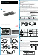
Since the signal range between a sensor and the PlantControl central unit is limited to a maximum of 200 
meters, repeaters with a signal range of up to 3 kilometers have been developed. If several such 
repeaters are used, the signal range can be extended up to 30 km. Power is supplied by either an AC 
adapter or a solar cell. 


Configuration options 

Up to 30 repeaters can be connected with a PlantControl. 

Up to 10 repeaters can be connected to each other in a row 
(max. 30 km). 

Up to 5 repeaters can be connected to one repeater. 

Up to 60 sensors can be connected with a repeater. 

Note: 

The first repeater must be positioned within 200 meters from 
the PlantControl. 

No sensors may be assigned to the first repeater.  

A PlantControl system requires a minimum of two repeaters. 

Signal range is up to 3 km line-of-sight and dependent on the 
type of terrain. 

The repeater frequency band is 868 MHz. Therefore the 
PlantControl  as well as the sensors must be set to 868 MHz. 

Control button / Connections 

A. Power connection (power supply or solar cell) 
B. LED 
C. Control button 
D. Interface for external antenna (optional) 

Switching on/ switching off/ checking power supply 

Please  note  that  repeater  are  usually  delivered  with  built-in 
rechargeable batteries (8x AA). 

1.

Unscrew  the 4 screws and remove the front cover. 

2.

Attach  the  battery  connector  to  the  battery  holder  (see  picture). 
By doing so the repeater is switched on. 

3.

Mount the front cover. 

4.

Plug now the AC adapter or solar cell to the power connection. 

5.

To  switch  off  the  repeater  the  battery  connector  must  be 
removed from the battery holder. It is not enough to just pull out 
the AC adapter or solar cell cable. 

6.

Check  by  pressing  the  control  button,  whether  the  repeater  is 
receiving  sufficient  power.  If  the  LED  flashes,  the  repeater  is 
operational.  If  the  LED  does  not  flash  then  either  there  is 
currently not enough power available (if a solar cell is used, the 
repeater enters in a sleep mode if the battery voltage is < 8.2V in 
and  is  only  ready  for  operation  again  when  the  battery  voltage 
rises again) or the repeater is defective. 

Operating (check also chapter "Initializing the repeater") 

By  pressing  the  control  button,  the  repeater  sends  a  test 
message to the Plant Control. The test Telegram can be used to 
identify  the  repeater  (see  also  Plant  Control  menu  Sensors> 
Identify.) 

To  initialize  a  repeater,  hold  down  the  control  button  for  5 
seconds (see also chapter "Initializing the repeater"). 

Summary of Contents for PlantControl CX

Page 1: ...er and Soil Moisture Sensors Operating Instructions Ver 3 46 P O Box 4 6987 ZG Giesbeek Nijverheidsstraat 30 6987 EM Giesbeek The Netherlands T 31 313 880200 F 31 313 880299 E info eijkelkamp com I ht...

Page 2: ...mmissioning 11 Step 1 Switching on your PlantControl 11 Step 2 Configuring your PlantControl central unit 11 Step 3 Initializing a repeater 12 Step 4 Repeater settings 16 Step 5 Initializing the senso...

Page 3: ...the display and analysis of the measured data Optional accessories Solar cell with cable connection to the Data Logger PlantControl D central unit External antenna for enhanced signal reception Plant...

Page 4: ...e sensors require no maintenance and have no corrosion prone parts In developing the Plant Control D performance the ease of use and reliability were given the greatest priority General Features Up to...

Page 5: ...Soil temperature 0 1 C Sensors for soil moisture measurements at soil temperature range between 2 C to 50 C on request 5 Quick start guide At the office 1 Connect cable for mains connection or solar c...

Page 6: ...export functions via USB interface 11 Alarm LED 12 GPRS Terminal LED Flashes every 3 seconds when network connection is established 13 Busy LED Lights up when the central unit is busy operating panel...

Page 7: ...icture above shows the connection terminals for the mains Besides the phase P and the neutral line N a ground wire has to be used The power cable is fed through one of the cable entries and connected...

Page 8: ...l Switching on switching off checking power supply Please note that repeater are usually delivered with built in rechargeable batteries 8x AA 1 Unscrew the 4 screws and remove the front cover 2 Attach...

Page 9: ...ately CAUTION When you remove the sensor cover take care to put it back on the same sensor Sensor operation Please note that the sensors are usually supplied without installed batteries Switching on s...

Page 10: ...nsor has not been initialized yet LED stays on continuously Error The frequency band switch on the sensor has been changed and no longer matches the frequency band on the PlantControl unit switch off...

Page 11: ...e network numbers allocated by the system Radio channel The factory setting for the radio channel is 5 Channels 2 3 4 and 5 can be selected The channel number should only be changed if there is radio...

Page 12: ...unit Repeater 1 Repeater 2 Input 0 Input 2 Repeater 5 Repeater 4 Repeater 3 Input 3 Input 4 Input 5 1 Select Initialize Repeater OK button 2 Before initializing a repeater you must first make the foll...

Page 13: ...with repeater number 6 Example repeater number 3 Enter under in direction of Controller the number 1 as repeater number 3 is connected with the PlantControl central unit via repeater number 1 Enter un...

Page 14: ...ting removing repeater number 9 1 Switch off repeater number 9 by removing the battery connector from the battery holder It is not enough to just pull out the AC adapter or solar cell cable 2 Deactiva...

Page 15: ...of repeater configurations 15 PlantControl Central unit Repeater 1 Repeater 3 Repeater 2 PlantControl Central unit Repeater 1 Repeater 2 PlantControl Central unit Repeater 1 Repeater 3 Repeater 2 Rep...

Page 16: ...16 Step 4 Repeater settings Settings Repeater OK button Number of repeaters This is automatically assigned based on the number of initialized repeaters For this reason the figure should not be changed...

Page 17: ...the system so that clear allocation is later guaranteed between the sensor and the data record You can then initialize the next sensor If a sensor is not recognized fail will appear in the display In...

Page 18: ...sensor Deactivate OK button Use the cursor keys to move to the next or previous sensor and to deactivate another sensor If you want to initialize again a deactivated sensor proceed with steps 1 to 8 a...

Page 19: ...OK key 3 Email send To test your settings or to manually initiate a transmission select Email send followed by the OK key only after entering all the parameters The GPRS Modem will immediately transm...

Page 20: ...s PlantCare settings Data retrieval by SMS In addition to automatic data transmission the data required can also be sent to any e mail address by sending an SMS to the GPRS Modem Use the following pro...

Page 21: ...ically remove the SIM Card from the GPRS Modem insert it in a mobile phone and make a phone call Some providers also accept an outgoing message as an outgoing call If this is the case with your provid...

Page 22: ...nsor at least 1 yard from the controller and briefly press the sensor s On Off button After a few seconds the PlantControl unit s display will show the full identification of the corresponding sensor...

Page 23: ...reset so that the sensors will not require initializing again Initialize Code Input OK button Enter here the code obtained from the manufacturer for the activation of additional functions Alarm text D...

Page 24: ...s Areas of shade should be avoided To avoid erroneous measuring results caused by water logging the sensor should not be positioned in dips in the ground If a sprinkler system is used ensure that the...

Page 25: ...sensor tip yellow part in water felt must be wet 4 Insert the sensor cautiously Never rotate the sensor when inserting or pulling out as this may unscrew the yellow sensor tip 5 Water the area around...

Page 26: ...advisable to use several dripper with a correspondingly lower water outlet per plant in order to achieve a better distribution of water Plants are very adaptive and the roots will grow into those are...

Page 27: ...wireless sensor the radio link between the sensor and Plant Control D CX or FA central unit should not be disturbed Since the radio transmission can be disturbed by the water in the leaves or any oth...

Page 28: ...ber endings H n m n m t K 1 1 1 1 1 Standard soils from the Agricultural Research Institute LUFA Speyer n m 1 1 28 Standard Soils Analyses Data Sheet 9 11 Mean values of different batch analyses stand...

Page 29: ...ard soils 5 1 6 2 3 fine textured soils medium textured soils coarse sand 4 European Union soil texture pyramid classification German soil texture pyramid classification FAO soil texture pyramid class...

Page 30: ...inserted into the USB port of the PlantControl central unit By selecting the command Firmware update the firmware is automatically installed This can take up to 10 minutes Firmware Update GPRS If a n...

Page 31: ...6 Troubleshooting The numbers and values used in this table are only examples Content coming soon 31...

Page 32: ...signed matches the number on the sensor cover 8 Warranty Your dealer will issue a two year warranty for this product from date of purchase This warranty covers all substantial defects of the unit that...

Reviews: