


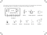

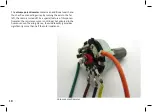


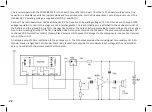


The eight-legged LM386 IC is a loudspeaker amplifier
suited for battery operation. Internally, it contains
many transistors and resistors.
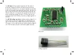
Pin 4 of the IC (GND) connects to the negative termi
-
nal of the battery via a 1 kΩ resistor (brown, black,
red) in order to limit the current in case of improper
assembly. The positive terminal is attached to pin 6
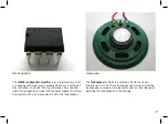
(Vs). Pin 5 is the output (Vout). Here, the loudspeak
-
er is attached via a 100 µF e-cap. This pin supplies
an average output voltage of approx. 4.5 V. Thus, the
positive terminal of the e-cap has to point towards
the IC and the negative terminal (marked by a white
bar) to the loudspeaker. Pins 2 and 3 are the inputs
of the amplifier and remain unattached for the time
being.
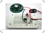
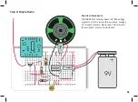
Let’s start with the first step and insert the compo
-
nents on the breadboard as shown in the illustration.
Inserting components in the breadboard requires
some force. The connection wires thus tend to bend.
It is important to insert the wires in a straight line
from above. Forceps or small pliers may come in
handy. Grip the wire a short distance above the breadboard und push it downwards. This way, you can even insert sensitive
wires like the tinned tips of the connecting wires of the battery clip or the loudspeaker without bending. If it is hard to insert
the wires, use a needle to widen the contacts on the breadboard a little.
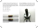
For the wire connections, you need hook-up wire. Cut appropriate lengths of wire and remove 5 mm of the insulation at the end.
You can strip off the insulation with your fingernails or with pliers. Alternatively, you can remove it with the help of a sharp knife.
12
Summary of Contents for RETRO RADIO
Page 1: ......
Page 14: ...14...
Page 15: ...Step 2 Sound Generator Required components 10 k resistor brown black orange 15...
Page 17: ...17...
Page 20: ...20...
Page 24: ...Step 5 Tuning Required components Hook up wire 24...
Page 29: ...29...
Page 35: ...Measured voltages 35...