EHC FUSION COMET 12 kW Installation & Technical Manual Download Page 6

 6

GB-031C_f.625

InsTallaTIOn

14. system protection

Failure  to  protect  the  system  will  invalidate  the  manufacturer’s 

warranty.

After the system has been installed the cleansing and inhibiting 

procedure must be carried out as follows:

Procedure:

1.  Fill  the  system  with  cold  mains  water  to  the  recommended 

pressure 1.5 bar and check for leaks, then drain the system 

thoroughly making sure all drain cocks are fully open and that 

the system is completely drained.

2.  Add Fernox Heavy Duty restorer through the header tank or 

via filling loop at the recommended dose. One bottle must be 

used as a minimum per dwelling. If you are unsure of the cor-

rect dose rate, contact Fernox.

3.  Re-fill the system and circulate the Heavy-Duty Restorer prior 

to the boiler being fired up, then commission the system in 

the normal way. The cleansing agent must be in the system 

for a minimum 1 hour with the system at normal operating 

temperature. A longer period of time would be more beneficial 

to the cleansing process especially if excess flux was used.

4.  Drain and flush the system thoroughly to remove the cleaning 

agent and any debris or contaminant. This is a critical part of 

the cleaning process and must be carried out correctly. Use a 

rinse test meter (TDS), such as the Fernox CTM. The reading 

must be within 10% of the mains ppm value.

5.  Then add the Fernox Protector (Copal MB1 or Super concen-

trate). This will protect against the formation of scale, corrosion 

and  microbiological  growths.  It  is  crucial  however,  that  for 

the protector to work correctly, the system must be properly 

cleansed and flushed.

6.  The label included within the Fernox Protector carton should 

be completed and attached adjacent to the boiler.

7.  We recommend inhibitor levels are checked on an annual basis 

(usually during the service) or sooner if the system content is 

lost. This should be carried out using a Fernox inhibitor Test 

Kit.

8.  Fernox Technical Service Helpline on 0870 870 0362 for further 

assistance.

15.  start-up / Commissioning

1.  Ensure the system is filled with water and correctly vented.
2.  Check  if  the  appropriate  system  installation  pressure  is 

reached(see the “TECHNICAL DATA” section). By using   or 

 but-tons whilst the control panel is off, the pressure value 

will be displayed. When the installation pressure is too low The 

“A’’indicator flickers (see “Operating’’ section). This doesn’t 

concern open vented system installations.

3.  Set the external controls to call for heat. Disconnect the flow 

sensor wiring plug on the control panel.

4.  Switch the boiler on (press   button).
5.  Check the pump is set to the correct mode (see table below). 

Todo this, press   button for no more than 2 seconds. The 

LED’sshould signal an operating mode at the place pointed by 

arrow.

6.  If the LEDs are signaling a different operating mode than rec-

ommended in the table below, set the appropriate mode ac-

cording to the following instructions: press   button for longer 

than 2 seconds, but less than 10 seconds (LED’s will start to 

flash),the pump then switches to the settings mode. LEDs glows 

to indicate the current settings. To change the settings of the 

pump in accordance with the table below, you can set the right 

combination of glowing LEDs by pressing 


the button. Once 

LED combination is set correct, by not pressing 


the button for 

10 seconds the pump will remember this setting and will exit 

from setting mode back to performance view.


note: holding


 button for more than 10 seconds will enter the 

pump into key lock mode. this prevents the user from altering 

the pump settings. To remove the key lock the pump settings and 

allow the pump settings to be changed, hold button


 again for 

more than 10 seconds.

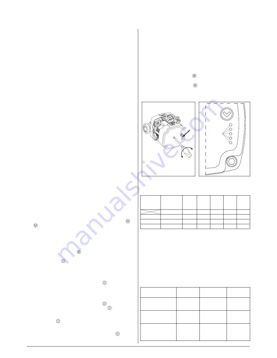
7.  Ensure  adequate  flow  through  the  boiler  is  reached  (the 

„H”indicator  is  on  with  a  constant  light).  The  pump  should 

self vent after a short period of running. if necessary assist the 

venting process in the following way; 

Warning the screw head 

in the centre of the pump is not intended to be used to assist 

venting of the pump, Damage to the pump internals may oc-

cur!

•  close the isolation valve on the outlet,
•  leave boiler running for 15 sec.
•  open the isolation valve.
8.  Switch the boiler off (hold   button for 3 seconds).
9.  Reconnect the flow sensor plug to the control panel.
10. Switch the boiler on (press   button).
11. Set the boiler to the required system temperature, see the “Op-

erating” section.

Figure 2  


Figure 3

LED


2   
3   
4   


LED

Rated 

power

[kW]

Pump lifting 

height [m]

LED 1

 red

LED 2

yellow

LED 3

yellow

LED 4

yellow

LED 5

yellow

4

6-9

5

9-12

6

14 - 24

7

alarm status

If the pump has detected one or more alarms, the bicolored LED 1 

switches from green to red. When an alarm is active, the LEDs indi-

cate the alarm type as defined in the table below. If multiple alarms 

are active at the same time, the LEDs only show the error with the 

highest priority. The priority is defined by the sequence of the table. 

When there is no active alarm anymore, the user interface switches 

back to operation mode.

Display

Indication

Pump 

operation

Counter 

action

One red LED + one 

yellow LED (LED 5)

Rotor is 

blocked.

Trying to start 

again every 1,5 

seconds

Wait or 

deblock the 

shaft.

One red LED + one 

yellow LED (LED 4)

Supply volt-

age too low

Only warning 

pump runs

Control the 

supply volt-

age

One red LED + one 

yellow LED (LED 3)

Electrical 

error

Pump is stopped 

because of low 

supply voltage or 

serious failure

Control the 

supply voltage 

/Exchange the 

pump

Summary of Contents for FUSION COMET 12 kW

Page 1: ...ate solution for central heating Installation technical Manual If you require any further assistance Telephone 01698 820533 Fax 01698 825697 E mail info electric heatingcompany co uk or visit our website www electric heatingcompany co uk ...

Page 2: ...er leaks into the boiler All plumbing joints must be checked The warranty card must be completed and sent back to The Electric Heating Company as soon as possible for registration An internal Magnetic Filter is fitted to the Boiler and it must be cleaned at least annually Note Failure to clean the Magnetic Filter may result in boiler shutdown Warranty calls will not be covered for this repair This...

Page 3: ...rovide an adequate fixing and should be fitted in a location that the boiler and pipe work are not subject to frost and damp conditions 3 Central heating design installation Detailed recommendations are given in BS EN 12828 2003 BS 6700 2006 A1 2009 and CP 342 2 1974 Pipes forming part of the useful heating surface should be in sulated to prevent any potential heat loss or frost damage BS 6700 199...

Page 4: ...om the heating system sealed systems Reference should be made to BS EN 14336 for the method of filling and make up of water There must be no direct connection between the boilers central heating system and the main water supply When mains water is required to fill the system directly all local water bylaws must be observed and any connection made must be disconnected after use 10 Flushing The syst...

Page 5: ...ure limiter 7 Return connection 8 Flow connection 9 Power Board 10 Control Module 11 Automatic Vent 12 Expansion Vessel and connection 13 By pass Valve 14 Magnetic Filter PF Internal mains phase connections from the PN connection block PN Incoming mains cable connection block WP Electric cable access M Boiler fixing points RP Room Thermostat volt free connection Electrical mains input ...

Page 6: ...e table below Todo this press button for no more than 2 seconds The LED sshould signal an operating mode at the place pointed by arrow 6 If the LEDs are signaling a different operating mode than rec ommended in the table below set the appropriate mode ac cording to the following instructions press button for longer than 2 seconds but less than 10 seconds LED s will start to flash the pump then swi...

Page 7: ...7 GB 031C_f 625 Temporary Filling Loop Mains Water Supply Temporary Filling Loop Mains Water Supply INSTALLATION Figure 5 Figure 4 ...

Page 8: ... supplying the property if other high power devices are used within the property E g Electric Showers If an electric shower is present we recommend that a Shower Sensor is installed within the system This will cause an interrupt to the boilers control signal when the shower is in use It will disable the boiler protecting the electrical system from overload All boilers must be protected at the mete...

Page 9: ...led sys tems At this point the main power may be switched on At this stage you may carry out the cleansing and protection of the system Refer to the installation section of this manual See page 7 Programmer Stat Connections The boiler PCB has a voltage free connection for the controls RP NA Under no circumstances should 240V be connected to these controller block connections as this will damage th...

Page 10: ...OOM THERMOSTAT VOLT FREE CONTROL CONNECTIONS TWIN CHANNEL PROGRAMMER DUAL CYLINDER THERMOSTAT ROOM THERMOSTAT VOLT FREE CONTROL CONNECTIONS 3A Switched Fuse Isolator 6 Amp 3A Switched Fuse Isolator 6 Amp EXTERNAL CONTROL WIRING Figure 8 Figure 9 ...

Page 11: ... Sensor connection Optional Figure 10 SAFETY NOTE RP Tzas and NA are signal conductors only DO NOT CONNECT ANY VOLTAGE to these as this will damage the boiler and invalidate the boilers warranty Tzas connections not used ZTD connections not used Room Thermostat ...

Page 12: ...12 GB 031C_f 625 EXTERNAL BOILER WIRING BOILER DIMENSIONS Figure 11 Return Inlet Flow Outlet Figure 12 ...

Page 13: ... external boiler interrupt active P Pump Indicator on pump is active proper flow rate of water has been reached Flickers lack of flow or insufficient flow rate of water heating elements are off Temperature Indicator Red light Boiler is in heating mode Green light Boiler temperature has been reached in radiators A Indicator flickers water pressure is not sufficient below 0 5 bar F When boiler is in...

Page 14: ... at any point in time then press the button a number of times until only indicator C is illuminated and then read the figure on the digital display 2 7 When indicator H is illuminated the pump is running 3 Temperature Setting We recommend the boiler temperature be set to 65 C Raise or lower the temperature in your installation with the buttons on the right hand side of the control panel as per 2 3...

Page 15: ...d be closed K indicator flickers Failure of inlet temp sensor Replace inlet temp sensor L indicator flickers Failure of outlet temp sensor Replace outlet temp sensor G H K Indicators lit but boiler not heating No supply to heating coils from Power Board Check outputs G1 G2 G3 on Power Board if 230Volts not present to all replace Power Board G H K Indicators lit but boiler only partially heating On...

Page 16: ...Electric Heating Company Ltd Unit 40 Block 5 Third Road Blantyre Industrial Estate Blantyre Glasgow G72 0UP Tel 01698 820533 Fax 01698 825697 www electric heatingcompany co uk www ehc renewables co uk ...

Reviews: