EGO CS1400E, Repair Manual Line
The EGO CS1400E Repair Manual Line is a comprehensive and user-friendly manual designed to assist in the repair and maintenance of the EGO CS1400E product. Available for free download, this essential manual provides step-by-step instructions and detailed diagrams, ensuring hassle-free repairs. Access it directly from manualshive.com.
Share
Download


Reviews:
No comments
Related manuals for CS1400E
814
Brand: ICS Pages: 15
G5000
Brand: Zenoah Pages: 15
FORMULA 60
Brand: Gardena Pages: 15
G5200
Brand: Zenoah Pages: 17
UC3050A
Brand: Makita Pages: 13
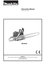
DCS 9010
Brand: Makita Pages: 28
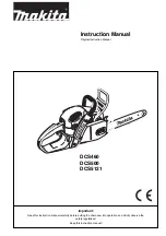
DCS460
Brand: Makita Pages: 32
DCS3500
Brand: Makita Pages: 32
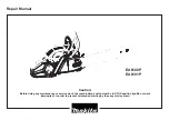
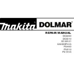
EA6100P
Brand: Makita Pages: 30
DCS460
Brand: Makita Pages: 32
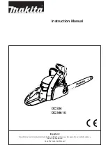
DCS34
Brand: Makita Pages: 28
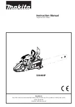
EA5600F
Brand: Makita Pages: 36
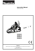
EA3500S
Brand: Makita Pages: 40
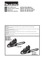
EA3600F
Brand: Makita Pages: 104
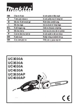
UC3530A
Brand: Makita Pages: 136
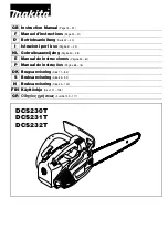
DCS230T
Brand: Makita Pages: 120
5014B
Brand: Makita Pages: 2
EA3200S
Brand: Makita Pages: 15


