

5
MAKE THE ELECTRIC CONNECTIONS
WARNING:
To avoid possible electrical shock, be sure
electricity is turned off at the main fuse box before
wiring.
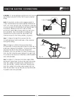
NOTE:
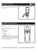
This remote control unit is equipped with 16
code combinations to prevent possible interference
from or to other remote units. The frequency switches
on your receiver and transmitter have been preset at
the factory. Please recheck to make sure the
switches on transmitter and receiver are set to the
same position, any combination of settings will
operate the fan as long as the transmitter and
receiver are set to the same position. (Figure 9)
Step 1.
(Figure 10) Insert the receiver into the
mounting bracket with the flat side of the receiver
facing the ceiling.
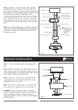
Step 2.
(Figure 11) Motor to Receiver Electrical
Connections: Connect the black wire from the fan to
black wire marked "TO MOTOR L". Connect the white
wire from the fan to the white wire marked "TO
MOTOR N" from the receiver. Connect the Blue wire
from the fan to the Blue wire marked "For Light" from
the receiver. Secure wire connections with the plastic
wire nuts provided.
Step 3.
(Figure 11) Receiver to House Supply Wires
Electrical Connections: Connect the black (hot) wire
from the ceiling to the black wire marked "AC in L"
from the receiver. Connect the white (neutral) wire
from the ceiling to the white wire marked "AC in N"
from the Receiver. Secure the wire connections with
the plastic wire nuts provided.
Fig. 9
Fig. 10
Code switch
ON
ON
Receiver
Hanger
bracket


