


Schmid & Wezel
D75433 Maulbronn,
Figure 1: Switching On/Off Z 079
Figure 2: Switching On/Off Z 080
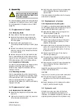
3.3 Working with the hook cutter
3.3.1 Cutting procedure
Ensure that the pump unit is in proper working
order and ready for operation.
Hold cutter firmly, place at the section you
wish to cut and operate the
switch (see chapter 3.2 "Operation of
switch " (page 4)).
For cutting, the meat can be suspended or placed
on a workbench. By positioning the cutter
properly where the meat is to be cut and by
operating
switch
a clean cut can
be achieved.
ON
OFF
ON
OFF
Never reach into the operating
range of the cutting blades, as
there is a risk of dismemberment!
Always wear goggles or other
effective eye protection!
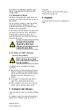
There is no need to bleed the hook cutter, as the
air is automatically released from the bleeding
filter of the pump unit after a number of cuts have
been completed.
For safety reasons, the holder of the cutter (20),
that can be mounted on either side must be
mounted on the side of the hand that holds the
material. For left-handed persons, it must thus be
on the right side, and for right-handed persons,
on the left (fig. 3).
Figure 3: Holding of cutter
The safety devices (holder (20) and bracket (29))
may not be modified or removed.
3.3.2 Operational safety
Hold hook cutter
at the
handle
Proceed with cutting; be very careful, as the
blades close
seconds after switching
on.
Cut meat at right angles; place blades (and not
just tips of the blades) onto the meat in order
to prevent overload and damage to blades.
For safe operation, the hook cutter should be
attached to a spring-loaded pulley system.
Place the cutter at right angles to the
meat you wish to cut. Ensure that the
meat is placed between the blades and
not just at the tips, as the blades might
otherwise break.
While the cutter is on, proceed
with special care caution and do
not reach between the blades.
under 1
Summary of Contents for Z079
Page 12: ...Schmid Wezel D 75433 Maulbronn A Anhang A 1 Massskizze...
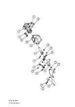
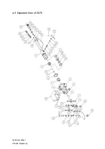
Page 16: ...Schmid Wezel D 75433 Maulbronn A 4 Explosionszeichnung Z079...
Page 17: ...Schmid Wezel D 75433 Maulbronn A 5 Explosionszeichnung Z080...
Page 18: ...Schmid Wezel D 75433 Maulbronn...
Page 19: ...Schmid Wezel D 75433 Maulbronn A 6 Explosionszeichnung Schlaucheinheit...
Page 31: ...Schmid Wezel D75433 Maulbronn A Appendix A 1 Dimension Drawing...
Page 35: ...Schmid Wezel D75433 Maulbronn A 4 Exploded View of Z079...
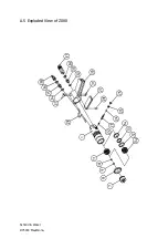
Page 36: ...Schmid Wezel D75433 Maulbronn A 5 Exploded View of Z080...
Page 37: ...Schmid Wezel D75433 Maulbronn...
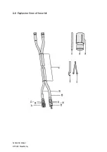
Page 38: ...Schmid Wezel D75433 Maulbronn A 6 Explosion View of hose kit...
Page 39: ......
Page 40: ......


