background image

4 / 10 


P/N 3100010 • REV 7 • ISS 04AUG10 

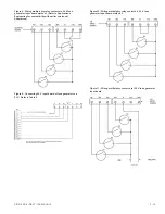
Figure 3:   Wiring to terminal block TB1 input circuit 


Figure 4:   Wiring the 5532M series speaker/amplifier 


Figure 5:  Wiring the 5540M series tone generator 


Figure 6:  Wiring the 5540MV series tone generator with voice 
messaging 


Figure 7:  Wiring an open collector transistor to tone generator 
input board 


Summary of Contents for 5532M

Page 1: ...on SW3 overrides the tone programmed on SW4 The tone programmed on SW4 has the lowest priority and cannot override any other programmed tone Speaker Amplifiers are heavy duty stand alone signaling devices that operate from local power and sound a tone programmed at the Tone Generator Speaker direction and the output level are easily adjustable Up to 2500 of these Speaker Amplifiers can be connecte...

Page 2: ...eaker to the approximate desired position WARNING To ensure integrity of the Adaptatone assembly when adjusting the speaker direction make sure threads in the enclosure remain fully engaged and do not turn speaker more than 360 degrees from the original factory installed position Ensure that the 4 collar gaskets part number P 041930 0362 are in place on each cover screw before securing the signal ...

Page 3: ...e generator select the appropriate method of wiring to the input board from Figure 7 Figure 13 Connect the tone generator as shown d For 5532B AQ 5532BDV2 AQ and 5532BHV AQ models connect power source to the speaker amplifiers at TS2 Polarity must be observed for DC models e For 5532B Y6 5532BDV2 Y6 5532BHV Y6 and 5532B N5 models connect incoming power to wire leads from power supply For Y6 models...

Page 4: ...lock TB1 input circuit Figure 4 Wiring the 5532M series speaker amplifier Figure 5 Wiring the 5540M series tone generator Figure 6 Wiring the 5540MV series tone generator with voice messaging Figure 7 Wiring an open collector transistor to tone generator input board ...

Page 5: ...r to Applications Engineering for compatibility with earlier versions of Adaptatone Figure 9 Connecting 24 V input board of tone generator to a PLC Refer to Table 5 Figure 10 Wiring multiple dry relay contacts to 24 V tone generator input board method 2 Figure 11 Wiring multiple dry contacts to 120 V tone generator input board ...

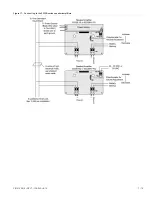
Page 6: ...to 120 V tone generator input board Refer to Table 5 Figure 13 Wiring audio output of tone generator to speaker amplifier audio coupler board Figure 14 5532M Series PC board locations Figure 15 5540M Series PC board locations Figure 16 5540MV Series PC board locations ...

Page 7: ...P N 3100010 REV 7 ISS 04AUG10 7 10 Figure 17 Connecting to the 5532B series speaker amplifiers ...

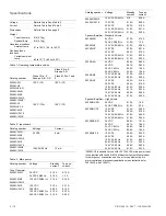
Page 8: ...6 125 VDC 250 VDC 120 VAC 50 60 Hz 240 VAC 50 60 Hz 0 10 A 0 02 A 0 10 A 0 10 A 0 20 A 0 10 A 0 31 A 0 20 A Speaker Amplifier Standard Volume 5532M AQ 24 VDC 24 VAC 50 60 Hz 0 10 A 0 10 A 0 74 A 1 3 A 5532M N5 120 VAC 50 60 Hz 0 10 A 0 36 A 5532M Y6 125 VDC 250 VDC 120 VAC 50 60 Hz 240 VAC 50 60 Hz 0 10 A 0 02 A 0 10 A 0 10 A 0 21 A 0 10 A 0 32 A 0 20 A 5532B AQ 24 VDC 36 VDC 24 VAC 60 Hz 24 VAC 5...

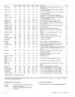
Page 9: ...Whoop OFF OFF OFF ON OFF ON 600 1250 Hz upward sweep in 4 s and repeat 05 Beep OFF OFF OFF ON ON OFF 470 Hz 0 55 s on 0 55 s off 06 Chime 1 OFF OFF OFF ON ON ON 700 Hz percussive repeat at 1 Hz 07 Fast Whoop OFF OFF ON OFF OFF OFF 600 1250 Hz upward in 1 s and repeat 08 Hi Lo OFF OFF ON OFF OFF ON 780 to 600 Hz alternately 0 52 s each 09 Rapid Siren OFF OFF ON OFF ON OFF 600 1250 Hz up and down sw...

Page 10: ...OFF OFF 1207 Hz and 493 Hz alternately 0 002 s each 2C Warning 2 ON OFF ON ON OFF ON 2336 Hz and 493 Hz alternately 0 005 s each 2D Warning 2 Beep ON OFF ON ON ON OFF 0 500 s of 2336 Hz and 493 Hz each alternating for 0 005 s followed by 1 s delay 2E Caution ON OFF ON ON ON ON 453 Hz for 0 040 s 235 Hz for 0 020 s 235 Hz for 0 160 s 260 Hz for 0 050 s 260 Hz for 0 1009 s 235 Hz for 0 050 s 2F Mult...

Reviews: