- 6 -
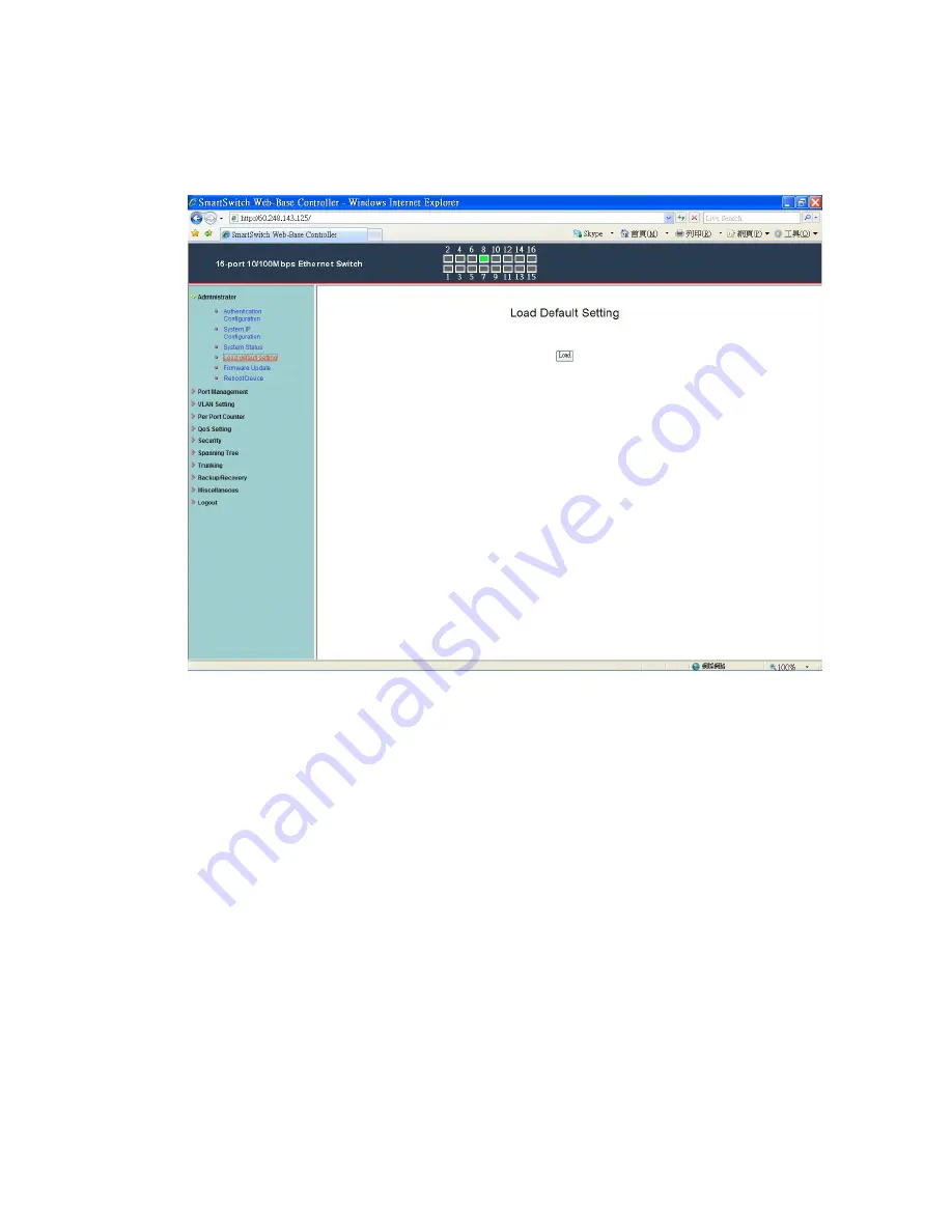
Administrator: Load Default Setting
1.
Click “Load” to back to the factory default setting.
**Note: Recover switch default setting excluding the IP address, User name and Password. Now, the default is loaded.
Page 1: ...0 16 Port Nway Fast Ethernet PoE Web Smart Switch User s Manual Ver 1 3 3...
Page 2: ...configure this Web Smart switch Step 1 Use a twisted pair cable to connect this switch to your PC Step 2 Set your PC s IP to 192 168 2 xx Step 3 Open the web browser like IE and go to 192 168 2 1 Then...
Page 3: ...ion procedure the home page shows up Select one of the configurations by clicking the icon Administrator Port Management VLAN Setting Per Port Counter QoS Setting Security Spanning Tree Trunking Backu...
Page 4: ...3 Administrator Authentication Configuration 1 Change the user name and the password 2 Click Update to confirm the new change Now you can use the new user name and the password...
Page 5: ...guration 1 Change the IP address type the new IP address or select DHCP IP configuration 2 Click Update to confirm the new change Setting Process OK will be shown on the screen Now the setting of Syst...
Page 6: ...em Status MAC address and system version will be shown on the screen 1 Change the new comment of this switch by typing the new comment 2 Click Update to confirm the new change Now the setting of Syste...
Page 7: ...6 Administrator Load Default Setting 1 Click Load to back to the factory default setting Note Recover switch default setting excluding the IP address User name and Password Now the default is loaded...
Page 8: ...7 Administrator Firmware Update Follow the instruction on the screen to update the new firmware Please contact with your sales agents to get the latest firmware information...
Page 9: ...8 Administrator Reboot Device 1 Click Confirm to reboot the device Now the setting of Reboot Device is finished...
Page 10: ...0M mode for the selected port 3 Duplex Full or Half Duplex mode for the selected port 4 Pause enable disable for the selected port 5 Backpressure enable disable for the selected port 6 Tx Cap Capabili...
Page 11: ...RX TX or TX RX from Source port to Destination port for analysis 1 Select the Destination port you can choose port 1 to port 16 2 Select the Source port by clicking the checking box of the port 3 Cli...
Page 12: ...ransmission rate of the selected port 0 Full speed 1 255 Specified bandwidth 3 RX Rate Value set the receiving rate of the selected port 0 Full speed 1 255 Specified bandwidth 4 Resolution Low 32 kbps...
Page 13: ...roadcast Storm Control 1 Threshold Set the threshold from 1 63 2 Enable Port per port to define the status of broadcast packets 3 Click Update to confirm the setting Now the setting of Broadcast Storm...
Page 14: ...POE of the port is able to supply power to the attached PD Powered Device 2 PSE Current Minimum Output Power The status of the port current and minimum output power 3 POE class each POE port will dete...
Page 15: ...o VLAN modes Port Based VLAN and Tagged VLAN Click Change VLAN mode to select the mode If the Port Based VLAN function is enabled Multi to 2 setting and tag Based VLAN will be disabled automatically N...
Page 16: ...an select a port group 1 Click the port numbers which you want to put them into the selected VLAN group 2 Click Update to confirm and finish the setting 3 Click LoadDefualt to back to the original fac...
Page 17: ...y setting the switch VLAN into VLAN Per Port 1 Choose Destination Port No 2 Choose Disable Port 3 Disable Port choose the port which you don t want to use 4 Click Update to confirm and finish the sett...
Page 18: ...17 Per Port Counter Counter Category You can read the transmitting and receiving packet of the connecting port Click Refresh or Clear the data...
Page 19: ...ing packet will be firstly transmitted 2 All High before Low All packets will be assigned to either Q2 high piority queue or Q1 low priority queue 3 4 Queue WRR Weight Round Robin set the ratio of the...
Page 20: ...19 QoS Setting Class of Service...
Page 21: ...based on the number of 4 Queue WRR on QoS Setting Priority Mode WRR Q1 Q2 Q3 Q4 Drop packets will be dropped 2 IP TOS DS Priority Setting Q1 Q4 IP TOS DS Port Setting It means the packets with specia...
Page 22: ...to activate on the selected port 1 Choose Select Port port 1 16 2 Binding Enable allow the packet with the specified source MAC address to enter this port 3 Click Update to confirm and finish the set...
Page 23: ...r Configuration You can enable or disable this function of per port If the Function Enable is Enable please kindly check the following setting 1 Port Filtering Rule Deny the outgoing packets to the se...
Page 24: ...h is connected to the server b Once this function is enabled the switch will check the destination TCP UTP port number at the outgoing direction of the secure WAN port If the condition matches this pa...
Page 25: ...ge configuration messages 4 Set the Max Age Indicates when the current configuration message should be deleted 5 Set the Forward Delay time Provides the length of time that bridges should wait before...
Page 26: ...25 Spanning Tree STP Port Settings 1 Choose Port No Port 1 Port 16 2 Choose Priority 0 240 3 RPC Root Path Cost 0 AUTO When the loop is found the STP RSTP will calculate the cost of its path...
Page 27: ...two groups to choose and max for each group is 4 ports Click Submit to confirm and finish the setting State Enable Disable Type LACP Static Activity Active Passive Both switches use LACP to configure...
Page 28: ...up Recovery Follow the instruction on the screen to update the original setting Backup Click Download to confirm the setting Recovery select a file and key in the password Click Update to confirm the...
Page 29: ...into different milliseconds or disable this function 2 VLAN Striding You can enable disable this function 3 IGMP Snooping V1 V2 You can enable disable this function 4 VLAN Uplink Setting Set uplink1 o...
Page 30: ...29 Logout You can click Logout to logout...