8-52
6205s2 BATHYMETRIC AND SIDE SCAN SONAR
0025262_REV_A
11.
Now, choose
Setup
from the top menu and then
Serial port.
12.
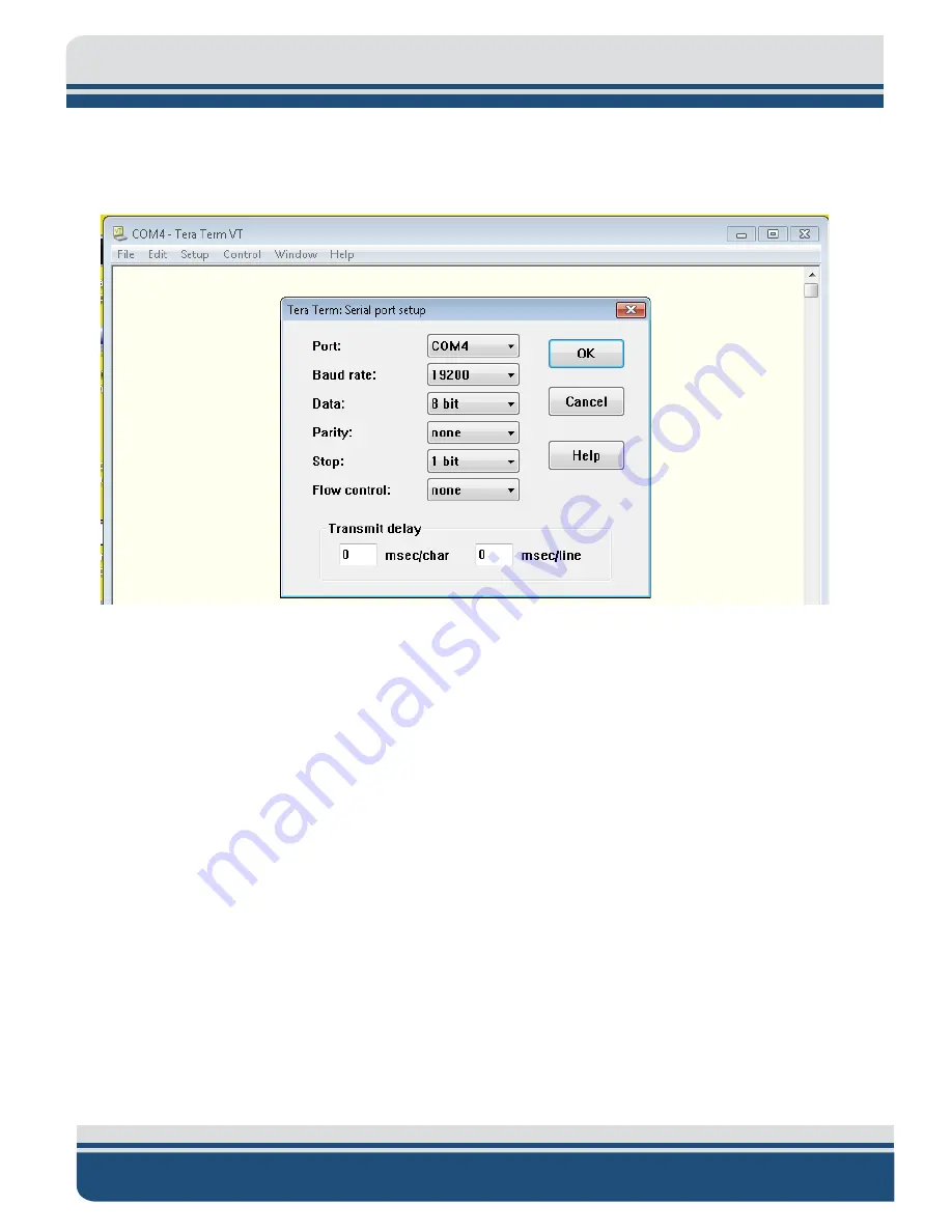
Configure the serial port options as shown in
and then click
OK
.
Figure 8-5: COM4 Port Settings
13.
Input the following commands:
Press <Enter> to start communications to SV sensor.
Type in “
SET STARTUP NOHEADER
” and press <Enter>.
Type in “
SET SV FORMAT 42
” and press <Enter>.
Type in “
SET SAMPLE 1/S
” and press <Enter>.
Type in “
SET DETECT 06
” and press <Enter>.
14.
Cycle the power on the Sonar Head using the On/Off switch on the interface box. Allow the sonar
to be off for at least 10 seconds before turning it back on.
15.
Reconnect to the sonar via the Remote Desktop and check COM4 using the Sonar application as
before in steps 3 and 4 above. SV data should not be scrolling as in:
Summary of Contents for 6205S2
Page 32: ...2 32 Figure 2 2 6205s2 Sonar Head with Adaptor Flange ICD...
Page 33: ...2 33 Figure 2 3 6205s2 Side Scan Transducer...
Page 34: ...2 34 Figure 2 4 6205s2 Side Scan Transducer Details...
Page 35: ...2 35 Figure 2 5 6205s2 Deck Cable Wiring Diagram...
Page 36: ...2 36 Figure 2 6 6205s2 GNSS INS Deck Cable Wiring Diagram...
Page 37: ...2 37 2 6 2 6205s2 Topside Figure 2 7 6205s2 Rack Mounted Topside...
Page 38: ...2 38 Figure 2 8 6205s2 Rack Mount in Case...
Page 41: ...3 41 3 1 2 2 Sonar Processor Endcap and Pinout Drawings Figure 3 5 6205S2 Forward End Cap...
Page 42: ...3 42 6205s2 BATHYMETRIC AND SIDE SCAN SONAR 0025262_REV_A Figure 3 6 6205s2 Aft End Cap...
Page 46: ...3 46 Figure 3 11 6205s2 Acoustic Center Location X Y Z and Bolt Pattern...
Page 47: ...3 47 Figure 3 12 6205s2 with Adaptor Flange Acoustic Center Location X Y Z and Bolt Pattern...


