4-42
2050-DSS SIDE SCAN AND SUB-BOTTOM SYSTEM
0024048_REV_A
The factory acceptance and verification tests for this sensor are run at a magnetically quiet site. They
include running hard iron and soft iron compensations once the sensor is installed in the towfish, followed
by verification to check the accuracy of the output relative to true north. In order to accommodate these
tests, a fixture is used that in conjunction with the stable sensor output, allows any misalignments
between the mounted sensor and the towfish longitudinal axis to be measured. The resultant offset is
applied as a correction in the sensor software as part of the AHRS verification procedure. Each towfish is
accompanied by an AHRS verification certificate, which confirms that the towfish AHRS meets
specifications.
Customer Options For Applying Magnetic Declination
The sensor unit that provides heading has the ability to take a local latitude and longitude and apply a
local magnetic declination adjustment to the heading measurements, thus providing true north
measurements as outputs. Edgetech offers two options to configure this, with the first being preferred as
there are fewer potential points of error.
1.
The latitude and longitude that lie on one of the agonic lines (zero magnetic declination) will be
entered prior to shipping the system. This means that effectively no magnetic declination will be
applied to the raw heading data, such that any magnetic declination corrections can be applied in
post-processing.
2.
Alternatively, the user can enter local latitude, longitude, and date, for the area in which they are
operating and apply magnetic declination before outputting heading data from the sensor. This
method requires that the user run the Ellipse Calibration Application on the towfish to enter and
save each new site's settings. If the user incorrectly applies the settings or simply forgets to do
this and leaves the settings from a previous site, the heading measurements will be incorrect. If
this option is chosen, please contact
4.7
Tow Vehicle Bridle Removal, Adjustment, and Installation
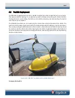
The 2050-DSS is delivered with a tow bridle that provides for towing the vehicle with an armored tow
cable behind a vessel. The tow bridle can be tilted forward, back, or removed for shipping in storage. It is
delivered in a default position that provides a flat and stable tow in typical tow conditions. If conditions
differ, the bridle’s mounting position can be changed on the mounting rails to accommodate. Instructions
to remove, adjust and install the bridle are provided below.
4.7.1
Tow Bridle Removal
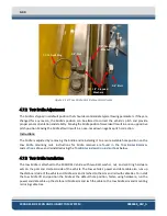
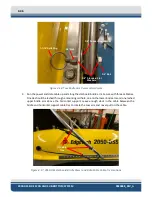
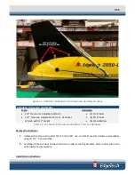
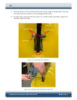
The Tow Bridle is attached to the 2050-DSS Vehicle with two bolt, washer, nut, and split ring hardware
assemblies on the port and starboard sides of the vehicle. The tow vehicle's power and data cable are run
up the starboard side of the vehicle and bridle arm and is lashed to the arm with cable ties. To remove
the bridle, unfasten the power and data cable from the bridle and unthread the hardware sets on the port
and starboard sides of the vehicle.


