3-2
2000-DSS Combined Sonar
0009335_REV_D
After unpacking the system components, be sure to safely store the shipping containers, including any
packing materials, for later use. When transporting or storing the system, all items should be packed in
their original shipping containers in the same manner in which they were originally shipped, and always
store the system in a dry environment when not in use.
3.2
Power Requirements
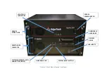
Power to the system comes in through the Rack Mount topside, which requires 90–260 VAC, 50/60 Hz.
The unit is auto switching.
3.2.1
Use of an Uninterruptable Power Supply
The AC power source should be continuously free of high amplitude, high frequency transients, as this
type of interference could cause degraded performance or damage to the equipment. An uninterruptable
power supply (UPS) with power surge protection is recommended for powering the equipment. However,
whether or not a UPS is used, the AC power source should never be the same as that being used to power
electric motors, such as pumps and winches, on the survey vessel. In addition, switching type battery
chargers or DC to AC converters with square wave outputs also should not be used.
3.2.2
Changing to a Non-US Power Plug
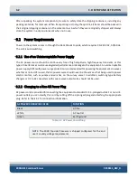
AC power cords is provided for connecting the equipment to standard U.S. 3-pronged outlet. For non-U.S.
power outlets you can modify this cord by cutting off the 3-pronged plug and attaching the appropriate
plug. Refer to
AC POWER CORD WIRE COLOR
FUNCTION
Black
AC line
White
AC neutral
Green
Earth ground
Table 3-1: AC Power Cord Wiring
NOTE:
The 2000 Topside Processor is shipped configured for the end
user’s country voltage requirements.
Summary of Contents for 2000-DSS
Page 20: ......
Page 56: ...Figure 4 2 2000 Digital Telemetry Link Electronics Block Diagram...
Page 57: ...Figure 4 3 2000 Digital Telemetry Link Wiring Diagram...
Page 59: ...Figure 4 4 Tow Vehicle Electronic Block Diagram...
Page 60: ...Figure 4 5 Tow Vehicle Interconnect Drawing...
Page 63: ...Figure 4 6 Armored Cable PMI Grip Unterminated Topside...
Page 64: ...Figure 4 7 Test Cable...
Page 77: ...5 13 Figure 5 16 Magnetic Declination Estimated Value Screen...
Page 79: ...5 15 getDeclination CR Figure 5 18...
Page 80: ......
Page 94: ......
Page 96: ......
Page 98: ......

