Quick Start Guide
– 3 –
Ground the AP
Ground the AP by connecting a ground wire to the grounding point on
the device and to nearby good earth.
Install the 5G Antennas
Install approved cellular 5G omni external antennas to improve coverage
and performance.
Connect Cables
a. Connect LAN Cables
1.
Connect Category 5e or better cable to the Uplink (PoE In)
1000BASE-T RJ-45 port. When connected to a PoE source, the
Uplink (PoE In) port connection provides power to the unit.
2.
(Optional) Connect a local LAN switch, computer or other device to
the LAN (PoE Out) 1000BASE-T RJ-45 port.
b. (Optional) Connect DC Power
When not connected to a PoE source, wire the included DC terminal plug
to a 10–24 VDC, 0.5-1 A source to provide power to the AP.
c. (Optional) Management Connections
Connect an RJ-45 to DE-9 straight-through console cable and then
configure the serial connection: 115200 bps, 8 characters, no parity,
one stop bit, 8 data bits, and no flow control.
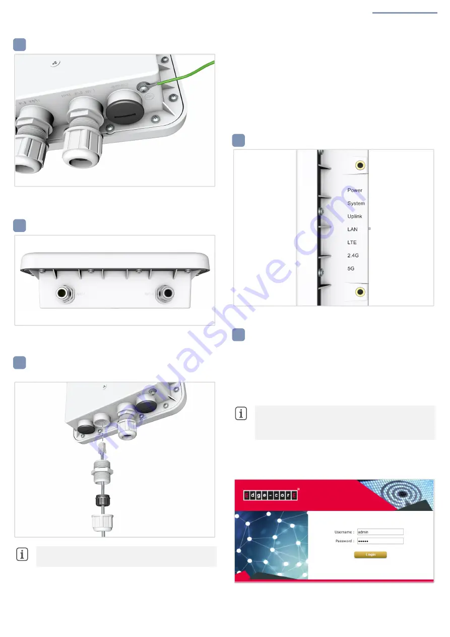
Check AP LEDs
Power and System LEDs—on green for normal operation.
Connect to the Web User Interface
1.
Connect a PC directly to the AP’s LAN (PoE Out) port.
2.
Set the PC IP address to be on the same subnet as the AP LAN port
default IP address. (The PC address must start 192.168.1.x with
subnet mask 255.255.255.0.)
3.
Enter the AP’s default IP address of 192.168.1.10 into the web
browser address bar.
4.
Log in to the web interface using default settings:
Username = admin
Password = admin
Note:
Port covers and cable glands should be tightned to a
torque of 10 kgf.cm.
2
3
3
Note:
To connect to the web interface using the Uplink (PoE
In) port, the IP address is automatically assigned through DHCP
by default. If a DHCP server is unreachable, the Uplink(PoE)
port reverts to a fallback IP address of 192.168.1.10.
4
5


