Web Configuration
3-9
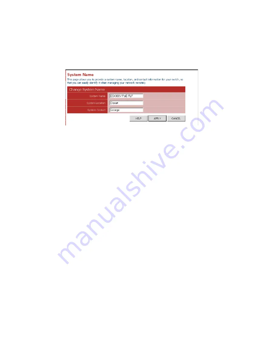
Displaying the System Name
You can easily identify the system by displaying the device name.
Field Attributes
•
Switch Name
– A name assigned to the switch system.
Web
– Click System, Name.
Figure 3-5 System Name
Setting the Switch’s IP Address
This section describes how to configure an initial IP interface for management
access over the network. The IP address for this switch is 192.168.2.10 by default.
To manually configure an address, you need to change the switch’s default settings
(IP address 192.168.2.10 and netmask 255.255.255.0) to values that are compatible
with your network. You may also need to a establish a default gateway between the
switch and management stations that exist on another network segment (if routing is
not enabled on this switch).
Field Attributes
•
DHCP Enabled
– Check the box to enable DHCP. (default: enabled)
•
LAN IP Address
– Address of the VLAN interface that is allowed management
access. Valid IP addresses consist of four numbers, 0 to 255, separated by
periods. (Default : 192.168.2.10)
•
Subnet Mask
– This mask identifies the host address bits used for routing to
specific subnets. (Default: 255.255.255.0)
•
Gateway IP Address
– IP address of the gateway router between this device and
management stations that exist on other network segments. (Default: 0.0.0.0)
•
Management VLAN
– ID of a configured VLAN (1-4093, no leading zeroes)
through which you can manage the switch. By default, all ports on the switch are
members of VLAN 1. However, the management station can be attached to a port
belonging to any VLAN, as long as that VLAN has been assigned an IP address.
Note:
If you cannot remember the switch’s IP address, you can restore the original
settings by following the procedure described in the “Troubleshooting” section.
Summary of Contents for ES4308-POE
Page 1: ...Powered by Accton Management Guide ES4308 PoE 8 Port Web Smart PoE Switch www edge core com ...
Page 2: ......
Page 4: ...ES4308 PoE E082007 DG R01 149100036400A ...
Page 8: ...iv Tables ...
Page 10: ...Figures vi ...
Page 14: ...Initial Configuration 2 2 ...
Page 21: ...Web Configuration 3 7 Web Click STATUS Overview Figure 3 3 Switch Information ...
Page 45: ...Web Configuration 3 31 Web Click PoE Settings Figure 3 28 POE Configuration ...
Page 46: ...Configuring the Switch 3 32 ...
Page 51: ......


