background image


Page 

26


4.4 

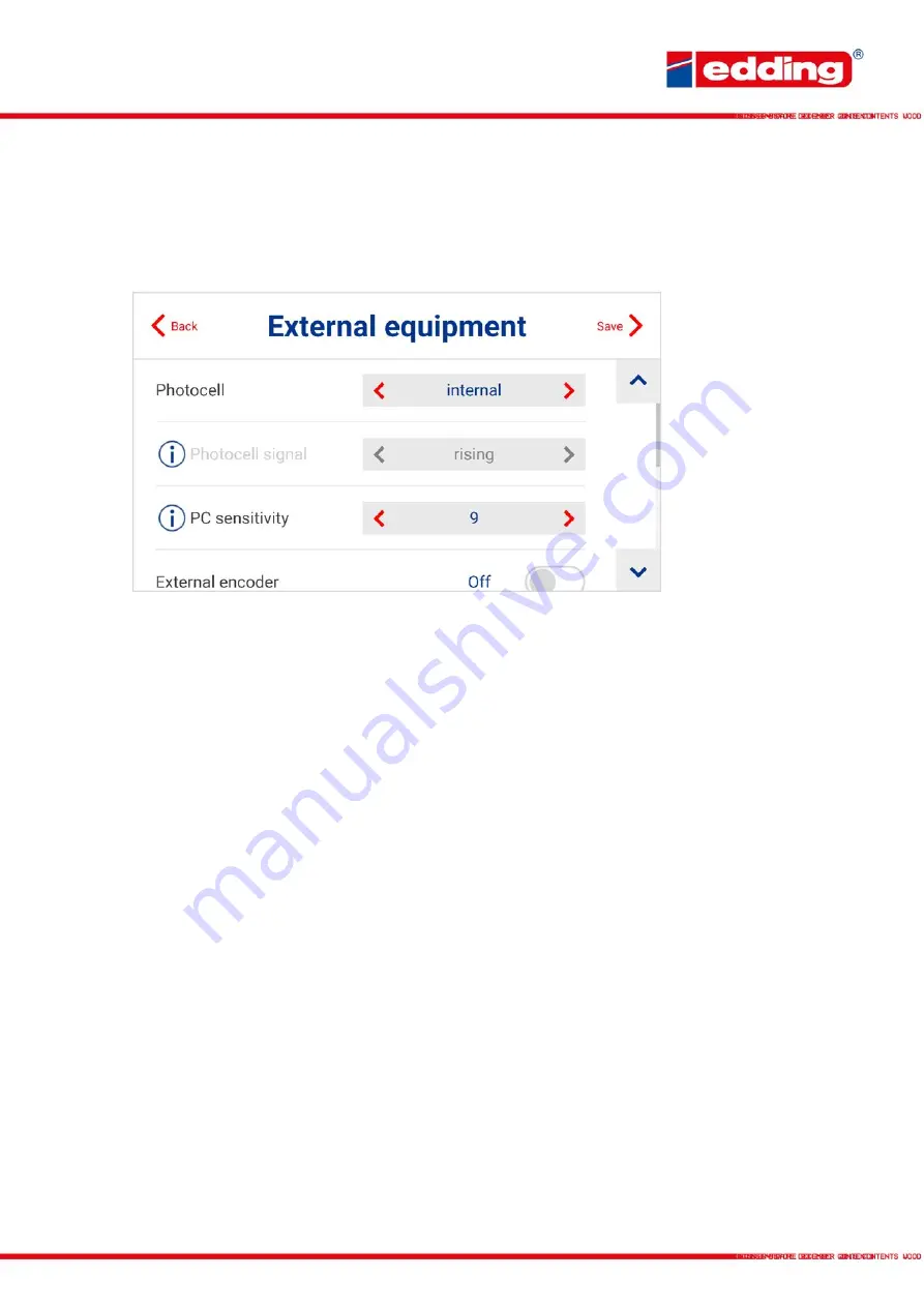
External equipment 

Settings for using external equipment such as the edding rotary encoder or the edding 
photocell. 


Photocell:

 Selection of whether the internal or external photocell should be used for printing. If 

an external photocell is connected, “PC 1” or “PC 2” must be selected here. These refer to the 
respective inputs of the printer PC 1 and PC 2. 

Photocell signal: 

Defines whether the printing should start on the rising or falling trigger signal. 

In simple terms: Whether printing should start when the photocell is dark (rising) or when this is 
free again after the product (falling). 

PC sensitivity: 

Only for internal photocell. Can be adjusted for material properties. The mean 

value is 9, values below 7 and above 11 are only required in exceptional cases. 

External encoder: 

Selection of whether the accessory “external rotary encoder” is connected to 

the printer. If not, the system prints at the configured conveyor speed. 

Pulse / Rotation: 

Number of pulses emitted by the external rotary encoder per rotation. If the 

standard edding rotary encoder is used, this value is set at 2.500 pulses. 

Diameter: 

Measuring wheel diameter of the external rotary encoder. If the original edding rotary 

encoder is used, this value is 63,7 mm. 

Print speed: 

Speed at which the products pass the printer, if no external rotary encoder is 

connected. 
 

Hint for detecting the speed

: Mark a straight section of 3 meters on the conveyor belt. Measure 

the speed of a product over this meter (in seconds). Multiply 20 by the measured value and you 
get the current speed of the production line in meters per minute. 

Ticks: 

Cannot be changed. This represents the number of resulting encoder pulses per inch of 

feed (automatically calculated by the system). 


Summary of Contents for in-line 12

Page 1: ...www edding tech User manual edding in line...

Page 2: ...ew of all saved texts 15 3 2 Creating a new print message 17 4 Settings 19 4 1 Assistants Setup Instructions 19 4 2 General 20 4 3 Print 24 4 4 External equipment 26 5 Speed charts 27 5 1 Print speed...

Page 3: ...r for access from every workstation User interface Intuitive user interface with real WYSIWYG print preview Automatic wizards for printer set up Step by step graphic tutorials for set up and maintenan...

Page 4: ...embly notes To assemble the system please read the step by step section above the graphical representation or the graphic step by step tutorial stored on the printer settings mounting instructions Ens...

Page 5: ...er so that you keep a print distance of max 6 8 mm to the print object 7 Insert cartridges at an angle approx 15 and lock with the fixing lever If excessive dust and ink accumulate on the print head c...

Page 6: ...f the printer Touchscreen Central control panel of the printer can be operated by touch or using the wireless keyboard supplied Accessory ports PC1 PC2 Printing triggered by an external photocell for...

Page 7: ...such as keyboards or USB data carriers Power supply Connection socket for the external mains adapter C14 DC connector 5 5 2 1 mm Only use original mains adapter with 24 V and 2 5 A Connection for gro...

Page 8: ...x AAA batteries included Keyboard USB receiver und 2x AAA batteries The USB receiver is located in the battery compartment on the back Open the lid remove the USB receiver from the compartment insert...

Page 9: ...ate and time Selection of the print direction is defined from the rear of the printer From right means the products move from right to left on the printer To use an external rotary encoder confirm sel...

Page 10: ...tridge currently used Colour of the dot indicates the colour of the ink Remaining volume of current cartridge in From 10 the warning low ink is displayed on the status LED Actual date dd mm yy and tim...

Page 11: ...to print mode The image currently in the preview is sent to the print processor and printing starts Press again to pause the print mode The name of the current message The print delay of the current...

Page 12: ...liliter ml Ink remaining Current fill level of the inserted cartridge Total prints per cartridge Number of possible prints with inserted cartridge can only be displayed during printing Prints remainin...

Page 13: ...models you select the right cartridge type manually by the below menu By touching the ink cartridge type or the cartridge content in the control panel the cartridge settings menu opens Cartridge Choo...

Page 14: ...ption Shift Mousewheel Scroll the displayed message in the text field see chapter 2 5 and 3 2 Only possible in the browser Shift Arrow keys Change the position of the message field when creating the t...

Page 15: ...int text message by name incl start search Also partial matches will be displayed Preview screen of a created print text Select text as new text to be printed Edit text Delete print text Set print del...

Page 16: ...Page 16 Page display selection for the messages There are always 30 messages displayed per page They are sorted by the message name alphanumeric...

Page 17: ...er product triggering Logo Prints an image from the printer memory A new image is uploaded in the Logo assistant Dyn 2D Dynamic 2D codes that can be filled with any combination of static text date tim...

Page 18: ...nter s on screen keyboard can be used for input After input is complete confirm with ENTER Then each field can be freely positioned within the message the element to be positioned is pulsing blinking...

Page 19: ...ght of 300 pixels therefore this is also the maximum image height Firmware Update Firmware update of the printing system via Ethernet or USB To do this the USB stick must be formatted in FAT32 format...

Page 20: ...nscreen keyboard is displayed and used or not Keyboard layout Selection of the keyboard layout for the virtual onscreen keyboard Units of measurement Choice between metric mm cm m and imperial inch Ru...

Page 21: ...r management is switched off by default To switch user management on the admin password is required The main screen then shows the user management symbol A Admin E Editor O Operator Pressing the user...

Page 22: ...te Must be executed once before saving input validation Ethernet status State Show the current state UP or DOWN DNS Display of the DNS server for name resolution Gateway Display of the gateway of the...

Page 23: ...tion if necessary Validate Must be executed once before saving input validation Wifi status State Show the current state UP or DOWN DNS Display of the DNS server for name resolution Gateway Display of...

Page 24: ...ozzles malfunction an improved print image can be achieved by switching to left or right See also the clean cartridge wizard for cleaning dirty cartridges 4 1 Print direction Selection of the print di...

Page 25: ...e printed parameter values are removed from the queue A new print can be done if all parameters in the message have values in the parameter queue s endless single shot Combination of endless and singl...

Page 26: ...l cases External encoder Selection of whether the accessory external rotary encoder is connected to the printer If not the system prints at the configured conveyor speed Pulse Rotation Number of pulse...

Page 27: ...speed in m min Max horizontal resolution in dpi Max vertical resolution in dpi Number of encoder pulses in ppr with 63 7mm diameter 20 600 600 5000 30 600 600 5000 40 400 600 5000 60 300 600 5000 80 2...

Page 28: ...c All data are standard values and depend on the total text length and the content to be printed Field type Static field Static field Dynamic field Content Letter M Date dyn 2D Code 10mm with 4 variab...

Page 29: ...the PC to the Internet via Wi Fi and make the Ethernet LAN slot free for the printer 1 Connect the printer to the PC using the Ethernet LAN cable Plug the network cable Ethernet LAN into the PC and pr...

Page 30: ...en the network connections Click on the displayed connection unidentified network press the right mouse button and open in the Properties menu In the properties of Ethernet click check Internet Protoc...

Page 31: ...ess previously specified in the printer in this case 192 168 0 200 The same menu opens as on the printer itself From here the printer can now be monitored new texts can be created and selected and set...

Page 32: ...nt go Pin 4 24V 24 V supply voltage If possible please aim to switch potential free signals The maximum power drain of all external connectors shall not exceed 1 5 A You do not have to set PNP or NPN...

Page 33: ...te Pin 3 S_Y yellow Pin 4 S_G green Additional Edding relay cable pin assignment and corresponding cable color Illustration shows the connector view Part number LO E I RK PIN Cable color Pin 1 white P...

Page 34: ...or printing 2 After the article has been printed the UV lamp photocell detects the article and sends a signal to the control unit 3 The control unit will light the UV lamp to dry the print The printer...

Page 35: ...ked to ensure the cooling system function properly Do not irradiate the same area of the substrate objector production line for too long to avoid damage caused by high temperature Keep UV lamp at leas...

Page 36: ...4 http Requests Numerous printer functionalities can be accessed via http as well as via a TCP connection More details can be found in the following guide User Guide on connectivity data bases ERP PL...

Page 37: ...g a message To then change the content of these data fields you do not have to follow any complex commands We simply created 5 TCP ports that stand for each of the data fields Port 10001 for Param_01...

Page 38: ...is shut down incorrectly simply set the switch to 0 Correctly the printer is shut down via the button top right of the display Error The touch display does not respond to touch touch does not work Wit...

Page 39: ...ilable for an additional fee Any number of printers can be added by entering the printer s IP address They can then be operated independently of one another Once all printers have been added to the co...

Page 40: ......

Reviews: