Theory of Operation
Model 560H
function of any common-mode voltage which may
be present and is fed back to enhance the CMR of
the amplifier.
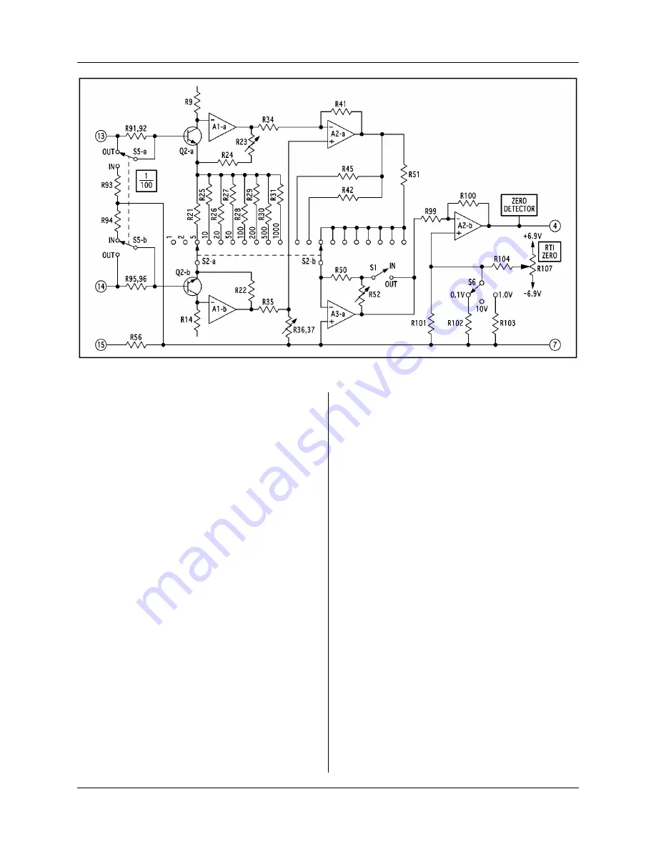
The outputs of A1 drive the inputs of the high-
level bridge differential amplifier A2-a. The bridge
resistors consist of R34 through R37, R39, R41,
and R97. Potentiometer R37 is used to balance the
bridge for optimum dc common-mode rejection.
The bridge resistors are scaled so that the amplifier
has a differential gain of
1. The output of A2-a is
connected to the inverting input of A3-a. A3-a has
a gain of
1 on gain step 1, a gain of
2 on gain
step 2, and a gain of
3 on steps 5 through 1000.
The output of A3-a is connected to the inverting
input of A2-b, the RTO-zero amplifier. The output
of that stage is fed to the amplifier wideband
output J1, Pin 4 by jumper Y-Z, and the filter and
100 mA output amplifiers if either or both of these
options are present.
CR12 and CR13 comprise a stable
6.9 V dc
power supply which is used to generate the voltage
for the three ranges of RTO zero. R105 and R106
provide the proper operating current for the two
precision zener diodes. Because the RTO
potentiometer R107 is connected directly across
the supplies, its wiper feeds a voltage of from
6.9
to
6.9 to R104. In the 10 V range, R104 forms a
voltage divider with R101 to inject the proper
voltage into Pin 5 of A2-b. In the 1 V RTO range,
R103 is placed in parallel with R101 to alter the
divider appropriately. Similarly, in the 0.1 V RTO
range, R102 is placed in parallel with R101.
FILTER AMPLIFIER (DRAWING 550-602)
The input to the filter-amplifier assembly, which
plugs into J2 on the main board, is connected to the
wideband amplifier output J1, Pin 4. The filter
amplifier output appears on J1, Pin 1. Both outputs
are available simultaneously. Switch S1 connects
various resistor and capacitor combinations across
the inputs of A1 to select the cut-off frequencies.
Potentiometer R11 adjusts the dc offset of A1 to
match the wideband output.
HIGH-CURRENT AMPLIFIER (DRAWING
563-603)
The current amplifier has unity gain and consists of
an input buffer A1 and a high-current driver A2.
The components are mounted on a plug-in board
which is installed on J3 of the main amplifier
assembly. Transistors Q1 and Q2 provide current
limiting. The current limit (130 mA) is established
6-2
Figure 6-1: Model 560H Simplified Amplifier Schematic


