background image


2.3 

Installation Procedures


2.3.1 

Install the Strap (Optional)


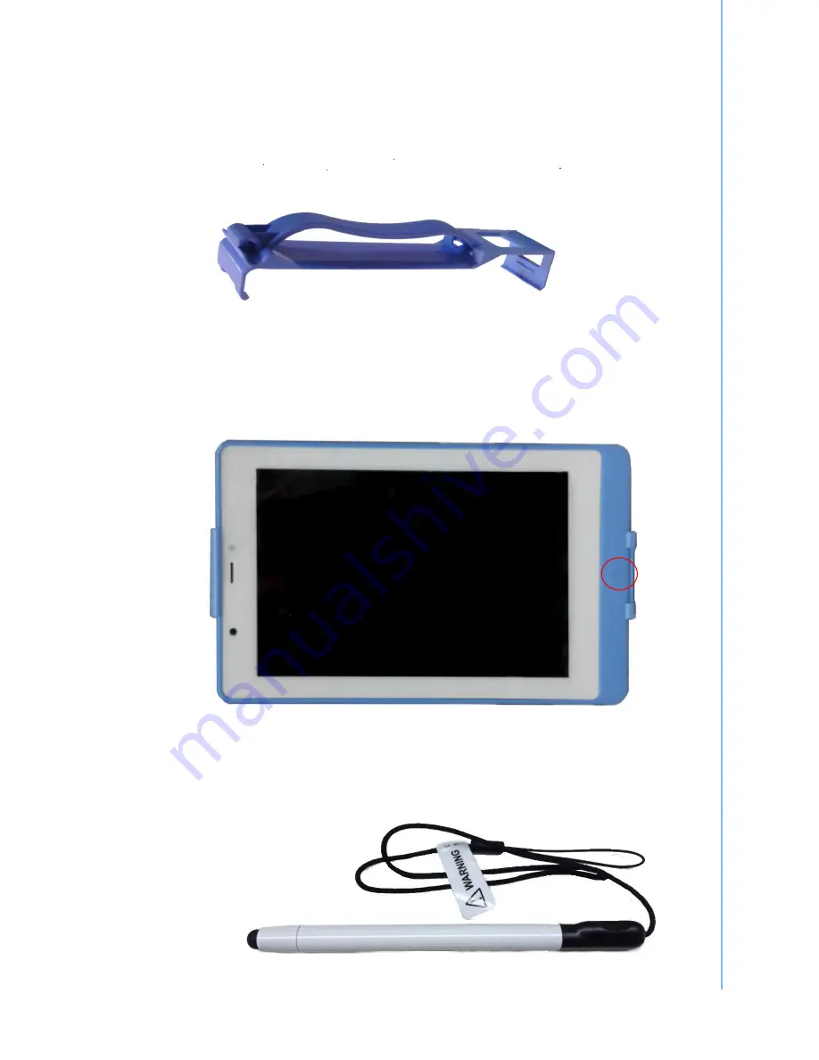
This strap is designed for the TB71A-W, which make the tablet convenient to hold.   

11 

TB71A-W Tablet PC User 

Manual 

Figure 2.8 Strap 


a.  Aim the triangle mark on the strap to the home key to slightly insert the bottom side of the 

tablet into the strap. 

b.  Press to insert the top side of tablet into the strap. 


2.3.2 

Insert / Hang the Stylus (Optional)


Figure 2.9 Install the Strap 


Figure 2.10 Stylus


Summary of Contents for TB71A-W

Page 1: ...User Manual TB71A W 7 Intel Atom based Pocketable pads...

Page 2: ...to provide reasonable protection against harmful interference in a residential installation This equipment generates uses and can radiate radio frequency energy and if not installed and used in accor...

Page 3: ...y approved by the relevant standards authority could void your authority to operate the equipment Attention Toute modification apport e l quipement qui n est pas express ment approuv par l autorit des...

Page 4: ...pheral attachments Description of your software operating system version application software etc A complete description of the problem The exact wording of any error messages This equipment is a sour...

Page 5: ...l a The power cord or plug is damaged b Liquid has penetrated into the equipment c The equipment has been exposed to moisture d The equipment does not work well or you cannot get it to work according...

Page 6: ...or data processing equipment IEC 60065 for video equipment IEC 61010 1 for laboratory equipment and IEC 60601 1 for medical equipment Furthermore all configurations shall comply with the system standa...

Page 7: ...TB71A W Tablet PC User Manual vi...

Page 8: ...g Station 10 Figure 2 8 Strap 11 2 3 Installation Procedures 11 2 3 1 Install the Strap Optional 11 Figure 2 9 Install the Strap 11 2 3 2 Insert Hang the Stylus Optional 11 Figure 2 10 Stylus 11 Figur...

Page 9: ...TB71A W Tablet PC User Manual viii...

Page 10: ...Chapter 1 1 General Information...

Page 11: ...s entertainment management and car park automation MICA is a reliable cost effective solution to meet an application s processing requirements 1 2 Specifications Table 1 1 TB71A W Specification Item D...

Page 12: ...LED Full Blue Charging Orange APD WA 20A05FU INPUT 100 240 V 0 6 A Max 50 60 Hz OUTPUT 5 V 4 A Chicony W12 010N3A INPUT 100 240 V 0 5 A Max 50 60 Hz OUTPUT 5 V 2 A Max Model MICA 071 Lithium ion batte...

Page 13: ...nol Do not autoclave or clean TB71A W or its peripherals with strong aromatic chlorinated ketone ether or other solvents sharp tools or abrasives Never immerse electrical connectors in water or other...

Page 14: ...1 4 Dimensions Figure 1 1 TB71A W Dimensions 5 TB71A W Tablet PC User Manual 121mm 200mm...

Page 15: ...TB71A W Tablet PC User Manual 6...

Page 16: ...Chapter 2 2 Getting Started...

Page 17: ...low When placed upright on the desktop the TB71A W front panel appears as shown in Figure 2 1 LED indicator Ambient sensor Camera Figure 2 1 Front View The volume control button barcode scanner button...

Page 18: ...right side of the tablet PC Barcode scanner button Figure 2 3 Right Side View The rear view of the tablet PC is depicted in Figure 2 4 Camera Camera flash Speaker Figure 2 4 Rear View 9 TB71A W Table...

Page 19: ...one jack Figure 2 5 Top View 2 2 A Quick Tour of TB71A W Docking Holder Optional When you place the docking station on the desktop its front panel appears as shown in Figure 2 6 Figure 2 6 Front View...

Page 20: ...venient to hold 11 TB71A W Tablet PC User Manual Figure 2 8 Strap a Aim the triangle mark on the strap to the home key to slightly insert the bottom side of the tablet into the strap b Press to insert...

Page 21: ...e make sure that the protective cover of docking port is placed right into its reserved slot Figure 2 12 Open and secure the protective cover 2 3 3 Insert the MICA into the Docking Station Optional 1...

Page 22: ...low these procedures in order 1 Insert the TB71A W into the docking station as previous section 2 3 3 See Figure 2 13 2 Connect the female end of the power cord to the DC in jack of the docking statio...

Page 23: ...into its reserved slot See Figure 2 12 2 Connect the docking end of the USB charge cable to the docking port of MICA See Figure 2 14 3 Connect the USB end of the USB charge cable to the USB charger 4...

Page 24: ...out notice No part of this publication may be reproduced in any form or by any means electronic photocopying recording or otherwise without prior written permis sion of the publisher All brand and pro...

Reviews: