ECS P6IWT-Me Manual Download Page 48

44

How to Flash a New BIOS

You can install an updated BIOS for this motherboard that you can
download from the manufacturer’ s website. New BIOS may provide
support for new peripherals, improvements in performance or fixes to
address known bugs. Install a new BIOS as follows:

1. Some mainboards have a Flash BIOS jumper that protects the

current BIOS from being changed or overwritten. If your mainboard
has this jumper, change the setting to allow flashing a new BIOS.

2. Some Setup programs have an item called Firmware Write Protect

that prevents the BIOS from being overwritten. If your BIOS has this
item (check the Advanced BIOS Features Setup page) disable it for
the present.

3. Your computer must be running in a real-mode DOS environment,

not the DOS window of Windows NT or Windows 95/98. We
recommend that you create a new formatted DOS system floppy
diskette.

4. Locate the flash memory utility on the support CD-ROM. It’ s called

AWD712.EXE. Copy this file to the new system diskette.

5. Copy the new BIOS file that you downloaded from the

manufacturer’ s website to the newly formatted system diskette.

6. Turn off your computer and insert the newly formatted DOS diskette

in your computer’ s diskette drive.

7. You might need to run the setup utility and change the boot priority

items on the Advanced BIOS Features Setup page, to force your
computer to boot from the floppy diskette drive first.

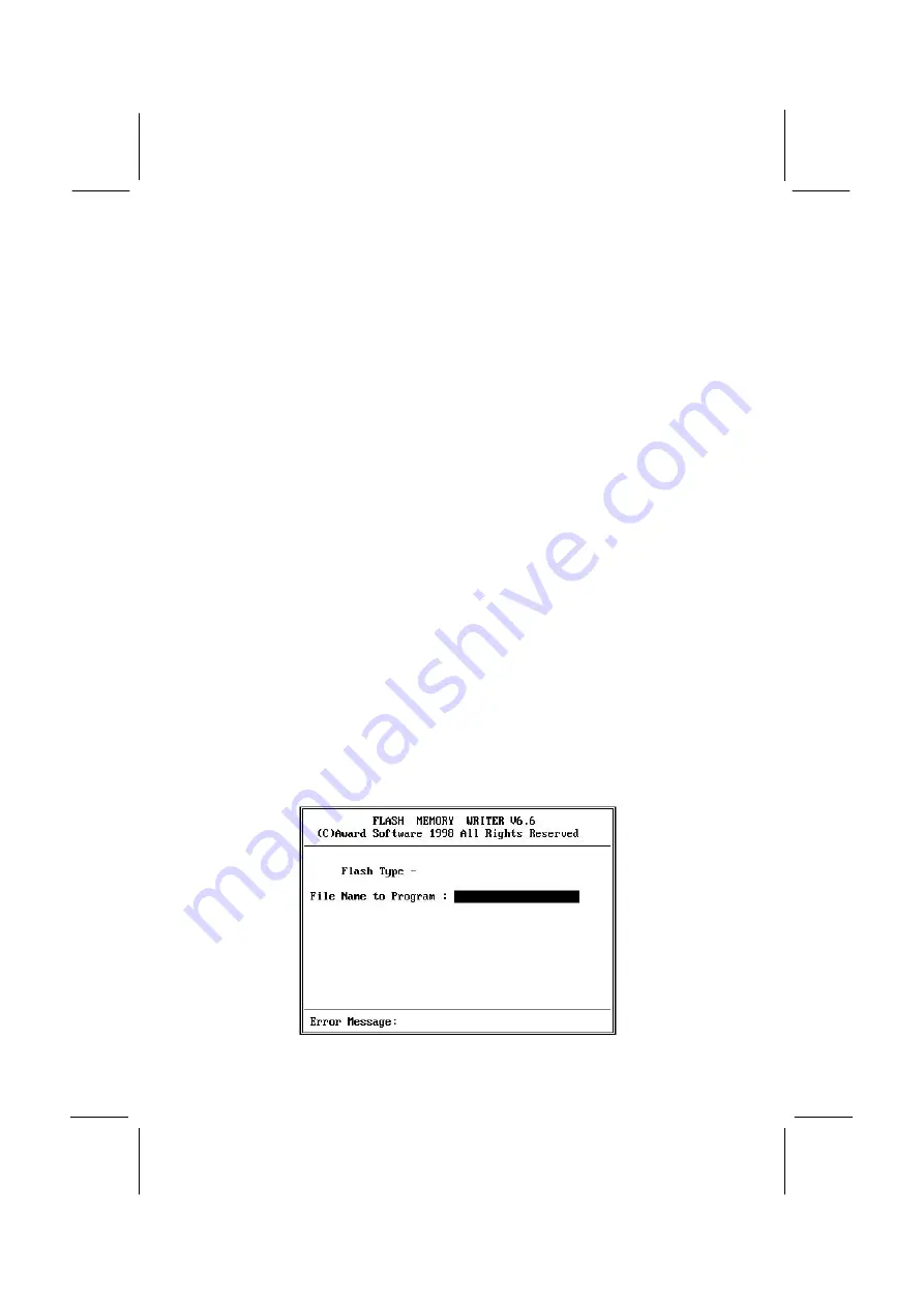
8. At the A:\ prompt, after your computer has booted a clean DOS from

the diskette, type in the filename AWD712 and press Enter.

Summary of Contents for P6IWT-Me

Page 1: ...fitness for any particular purpose Further the manufacturer reserves the right to revise this publication and to make changes from time to time in the content hereof without obligation of the manufact...

Page 2: ...separation between the equipment and the receiver q Connect the equipment onto an outlet on a circuit different from that to which the receiver is connected q Consult the dealer or an experienced radi...

Page 3: ...e Jumper Settings 16 Install the Mainboard in the Case 19 Connecting Power Chassis Fans Panel Case Open 21 Install Other Hardware 23 Install the Processor 23 Installing a Slot1 Processor 24 Installing...

Page 4: ...ion 60 Load Optimized Defaults Option 60 Set Supervisor and User Passwords 60 Save And Exit Setup Option 61 Exit Without Saving Option 61 Chapter 4 Software 62 About the Software 62 Folders for this M...

Page 5: ...ns The P6IWT Me is a micro ATX mainboard that uses 4 layer printed circuit board and measures 222mm x 244mm The mainboard features the new low cost Intel 810 chipset which includes an accelerated grap...

Page 6: ...ents that make this one of the best value mainboards on the market About the Manual The manual consists of the following chapters Introduction Use the Introduction Chapter to learn about the features...

Page 7: ...e automatic settings by making changes to jumpers on the mainboard or changing the settings in the system setup utility We strongly recommend that you do not overclock the mainboard to run processors...

Page 8: ...ith clock speed ranging from 266 MHz through 466 MHz For higher performance business class computing the slot 1 can be installed with a Pentium II processor cartridge The Pentium II has 32K of interna...

Page 9: ...odule Highly Integrated Design As well as the Intel 810 chipset the P6ITW Me features other highly integrated silicon chips The ITE LPC I O controller handles the mainboard s I O functions The CMI 873...

Page 10: ...nce the board includes built in networking built in fax modem and built in video and audio the three 32 bit PCI slots that are provided are more than adequate for expansion purposes Each of the three...

Page 11: ...etting of CPU parameters The fully programmable firmware enhances the system features and allows users to set power management CPU and memory timing LAN and modem wake up alarms and so on The firmware...

Page 12: ...n choosing a case avoiding static electricity damage and setting jumpers Preparing the Mainboard Provides a guide to the mainboard and I O port locations full details on the jumper settings and advice...

Page 13: ...pins 2 3 JP3 Keyboard power on jumper Use this 3 pin jumper to enable keyboard power on with hot keys or password Function Jumper Cap Enable keyboard power on Short pins 1 2 Disable keyboard power on...

Page 14: ...tatic electricity Ensure too that you are installing the mainboard into a suitable case Static Electricity In adverse conditions static electricity can accumulate and discharge through the integrated...

Page 15: ...that your case has sufficient power and space for all the drives that you intend to install The mainboard has a set of I O ports on the rear edge Ensure that your case has an I O template that support...

Page 16: ...ows the same 3 pin jumper The jumper cap is placed on pins 1 and 2 so this jumper setting is SHORT PINS 1 2 In this manual all the jumper illustrations clearly show the pin numbers When you are settin...

Page 17: ...he following illustration and key to identify the components on your mainboard JP3 CPUFAN1 ATX1 Slot 1 Socket 370 DIMM1 DIMM2 PWRFAN1 JP5 FDD1 IDE2 IDE1 CASFAN1 PANEL WOL1 WOM1 JP1 JP7 PCI1 PCI2 PCI3...

Page 18: ...r supply cooling fan CDIN1 Audio connector for CD ROM DVD drive CDIN2 Auxiliary audio connector for CD ROM DVD drive J3 Connector for Chassis Open Detect circuit J4 Connector for onboard modem extensi...

Page 19: ...port for pointing device upper port PS 2 port for keyboard lower port LPT1 External parallel port J2 Upper External game MIDI port J2 Lower Audio jacks for left to right line out line in microphone V...

Page 20: ...tings that are stored in CMOS memory You might need to erase this data if incorrect settings are preventing your system from operating To clear the CMOS memory turn off the system disconnect the power...

Page 21: ...to install a different audio system on a third party expansion card you must disable the onboard audio Function Jumper Cap Enable audio modem system Short pins 1 2 Disable audio modem system Short pi...

Page 22: ...mper Cap Turn on onboard codec Short pins 1 2 Turn off onboard codec Short pins 2 3 JP7 LAN enable disable Jumper This 3 pin jumper can be used to enable or disable the onboard network adapter If you...

Page 23: ...mainboard You can secure the mainboard in the system case by placing the mainboard over the mounting brackets and driving screws through the mainboard into the mounting brackets Note Do not overtight...

Page 24: ...20 The illustration below shows the mainboard installing into a tower type case Power Supply Unit Drive Cage Expansion Slots I O Template...

Page 25: ...L connector on the mainboard Power Connector Locate the power cable from the case power supply unit and plug it into the ATX1 power connector Chassis and Power Fans If your case has a cooling fan inst...

Page 26: ...r connectors that are commonly found on ATX system cases Use the illustration below to make the correct connections to the case switches and indicators PANEL Speaker 1 3 5 7 Power LED 2 4 6 KeyLock 8...

Page 27: ...tel Pentium II The Pentium II has a wide range of performance Pentium II processors have shipped with clock speeds of 233 MHz through to 450 MHz Currently you might find that stores only stock Pentium...

Page 28: ...ve than a SEPP Celeron with the same clock speed Installing a Slot1 Processor This board has a SLOT1 processor cartridge slot The slot must be installed with a cartridge holder that supports the proce...

Page 29: ...at sink which lock into the support bar The documentation supplied with the processor shows how to do this Install the Processor Cartridge After you have installed the cartridge holder follow the inst...

Page 30: ...r 1 On the mainboard locate the socket 370 and CPUFAN1 2 On the socket 370 pull the locking lever away from the socket to unhook it and then raise the locking lever to the upright position 3 Identify...

Page 31: ...cket 370 processor with heatsink cooling fan assembly The mainboard must be configured to deliver the correct clock speed and the correct system bus for the kind of processor that you have installed Y...

Page 32: ...You must install at least one memory module The first memory module must be installed in DIMM1 so that a portion of the memory can be shared with the graphics adapter A second module can be installed...

Page 33: ...ide of the device connector Each connector has the pin 1 side clearly marked The pin 1 side of each ribbon cable is always marked with a red stripe on the cable About IDE Devices Your mainboard has a...

Page 34: ...the cable that you use Make sure that you have the pin 1 side of the cable matched with the pin 1 side of the connector 4 Plug a power cable from the case power supply unit into the power connector o...

Page 35: ...ug a power cable from the case power supply unit into the power connector on the back edge of the CD ROM DVD drive 4 Use the audio cable provided with the CD ROM DVD drive to connect the audio connect...

Page 36: ...into the diskette drive interface on the mainboard FDD1 2 Plug one of the connectors on the diskette drive cable into the data connector on the back edge of the floppy diskette drive Make sure that yo...

Page 37: ...AMR slot PCI1 PCI2 PCI3 AMR 1 Before installing an expansion card check the documentation for the card carefully If the card is not Plug and Play you may have to manually configure the card before in...

Page 38: ...are before you can begin using the add in card PCI add in card PCI slot Edge connector Metal bracket Note If you have installed an AMR card you should check the settings of jumpers JP4 audio modem ena...

Page 39: ...through the network automatically resume the system You must enable this item using the Power Management page of the setup utility See Chapter three for more information WOM1 Wake on Modem If you hav...

Page 40: ...sion bracket SPDIF Fax modem Card You must install the fax modem card in order to use the built in fax modem The fax modem card is an optional item supplied with this mainboard 1 Locate the J4 fax mod...

Page 41: ...r on the mainboard 2 Remove a blanking plate from a free expansion slot in the system chassis 3 Plug the cable from the network adapter extension bracket onto the J6 connector 4 Install the metal brac...

Page 42: ...connected the cable secure the optional IR port to the appropriate place on your system case Note An IR port may use some of the resources required by a fax modem card If you have more than one of th...

Page 43: ...al audio devices If your CD ROM DVD drive has digital audio output you can connect it to the input pins of the SPDIF connector On the mainboard locate the digital audio connector SPDIF1 Connect the ca...

Page 44: ...T1 3 The upper 15 pin port J2 is a game MIDI port You can use this port to connect a joystick or a MIDI device to your system 4 The lower part of J2 is three audio jacks The left side jack is for a st...

Page 45: ...g VGA Blue Audio line in Light blue Audio line out Lime Digital monitor flat panel White IEEE 1394 Grey Microphone Pink MIDI Game Gold Parallel Burgundy PS 2 compatible keyboard Purple PS 2 compatible...

Page 46: ...sks you to make changes to the setup utility This happens when the system finds an error during the POST Power On Self Test that it carries out at start up Starting the Setup Utility You can only star...

Page 47: ...essing the Escape key You can save the current selections and exit the utility by pressing the F10 key When you are in one of the options that displays a dialog box you can return to the main menu by...

Page 48: ...it for the present 3 Your computer must be running in a real mode DOS environment not the DOS window of Windows NT or Windows 95 98 We recommend that you create a new formatted DOS system floppy diske...

Page 49: ...CMOS Features Option This option displays a table of items which defines basic information about your system Date and Time The Date and Time items show the current date and time held by your computer...

Page 50: ...defines some special ways that can be used to access IDE hard disks such as LBA Large Block Addressing Leave this value at Auto and the system will automatically decide the fastest way to access the...

Page 51: ...ducing fatal errors to your system Note that the page has a scroll bar to scroll down to more items Anti Virus Protection Default Disabled When this item is enabled it provides some protection against...

Page 52: ...Use these three items to select the priority and order of the devices that your system will search for an operating system at start up time Boot Other Device Default Enabled If you enable this item t...

Page 53: ...r the setup utility OS Select For DRAM 64 MB Default Non OS2 This item is only required if you have installed more than 64 MB of memory and you are running the OS 2 operating system Otherwise leave th...

Page 54: ...at the default value Memory Hole at 15M 16M Default Disabled This item can be used to reserve memory space for some ISA expansion cards that require it Delayed Transaction Default Enabled If the chips...

Page 55: ...lave device These four items let you assign which kind of PIO Programmed Input Output is used by IDE devices You can choose Auto to let the system auto detect which PIO mode is best or you can install...

Page 56: ...e or disable it AC97 Audio Default Disabled We recommend that you set this item to Enabled when you use AMR card AC97 Modem Default Disabled We recommend that you set this item to Enabled when you use...

Page 57: ...n Interrupt Request Line IRQ Parallel Port Mode Default SPP ECP Mode Use DMA Default 3 This item defines the operation of the parallel port As a default it is set to SPP standard parallel port If you...

Page 58: ...resumed by certain events Power Management Timeouts The power saving modes can be controlled by timeouts If the system is inactive for a time the timeouts begin counting If the inactivity continues so...

Page 59: ...the CPU will go into the Idle Mode Modem Use IRQ Default 3 If you want an incoming call on a modem to automatically resume the system from a power saving mode use this item to specify the interrupt re...

Page 60: ...llows you to set a date and time alarm that will automatically resume the system from a software power down When you enable this feature new setup items appear to let you set the alarm Date of Month A...

Page 61: ...required If you cannot get a legacy ISA Industry Standard Architecture expansion card to work properly you might be able to solve the problem by changing this item to Manual and then opening up the IR...

Page 62: ...st leave this item disabled PCI Health Status Option On mainboards which support hardware monitoring this item lets you set parameters for critical voltages critical temperatures and fan speeds If thi...

Page 63: ...processor that you have installed Set this item to the rated internal clock speed of the installed processor If you set this to Manual two new items appear CPU DRAM SPECTRUM Freq and CPU Core Bus Freq...

Page 64: ...reater than the performance level of the components such as the CPU and the memory You can cause fatal errors or instability if you install the optimized defaults when your hardware does not support t...

Page 65: ...u have made in the setup utility and exit the setup program When the Save and Exit dialog box appears press Y to save and exit or press N to return to the setup main menu Exit Without Saving Option Hi...

Page 66: ...P6IWT Me folder Note Never try to install software from a folder that is not specified for use with your mainboard Folders for this Mainboard For this board you can install software from the followin...

Page 67: ...nto the Intel 810 chipset P6IWT Me Folder You can use the software in the following sub folders q MONITOR Hardware monitoring software for Windows 95 98 and Windows NT4 0 5 0 q ACPI AUDIO LAN MODEM VG...

Page 68: ...Flash Memory Utility This utility lets you erase the system BIOS stored on a Flash Memory chip on the mainboard and lets you copy an updated BIOS to the chip Take care how you use this program If you...

Page 69: ...95 98 Installation Please specify the path to the CD ROM CMI8X38 AUDIO_ITE_GAME W95 98 DRV when your system detects the installed audio system To install the audio applications log on to the W95 98 fo...

Page 70: ...k adapter Log on to the LAN folder This folder has sub folders for many different operating systems including Netware DOS SCO UNIX Workgroups for Windows Windows 95 98 OS2 and so on Log on to the corr...

Page 71: ...stallation by running SETUP EXE Mainboard P6IWT Me Installation Notes Most of the sub folders in this folder are empty with a short README file giving directions to alternate folders for the appropria...

Page 72: ...n Jumper Cap Enable keyboard power on Short pins 1 2 Disable keyboard power on Short pins 2 3 JP4 Audio modem enable disable jumper Use this jumper to enable or disable the audio system and modem inte...

Page 73: ...enable or disable the built in network adapter Function Jumper Cap Enable onboard LAN Short Pins 1 2 Disable onboard LAN Short pins 2 3 Panel Connector The mainboard PANEL connector has a standard set...

Reviews: