


Chapter 3
A75F2-A2 USER MANUAL
47
Save Options
This item enables you to save the options that you have made.
Save Changes
This item enables you to save the changes that you have made.
Discard Changes
This item enables you to discard any changes that you have made.
Restore Defaults
This item enables you to restore the system defaults.
Save as User Defaults
This item enables you to save the changes that you have made as user defaults.
Restore User Defaults
This item enables you to restore user defaults to all the setup options.
Save Changes and Exit
This item enables you to exit system setup after saving the changes.
Discard Changes and Exit
This item enables you to exit system setup without saving any changes.
Save Changes and Reset
This item enables you to reset the system setup after saving the changes.
Discard Changes and Reset
This item enables you to reset system setup without saving any changes.
This page enables you to exit system setup after saving or without saving the
changes.
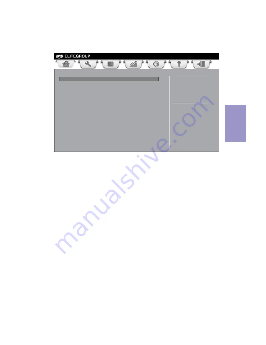
Save & Exit Menu
Main
Advanced
Chipset M.I.B III Boot Security
Save & Exit
+/- : Change Opt.
Enter/Dbl Click : Select
lk
mn
: Select Screen
/Click: Select Item
F1: General Help
F2: Previous Values
Go back to EZ Mode.
F3: Optimized Defaults
F4: Save & Exit
ESC/Right Click: Exit
Back to EZ Mode
This item enables you to back to EZ mode.
Back to EZ Mode
Load Non Disk Utility
Save Changes and Exit
Discard Changes and Exit
Save Changes and Reset
Discard Changes and Reset
Save Options
Save Changes
Discard Changes
Restore Defaults
Save as User Defaults
Restore User Defaults
Boot Override