ECS 661FX-M Deluxe Manual Download Page 40

35

35

35

35

35

Using the Motherboard Software

Chapter 4
Using the Motherboard Software

About the Software CD-ROM

The support software CD-ROM that is included in the motherboard package con-
tains all the drivers and utility programs needed to properly run the bundled prod-
ucts. Below you can find a brief description of each software program, and the
location for your motherboard version. More information on some programs is
available in a README file, located in the same directory as the software.

Never try to install all software from folder that is not specified for use
with your motherboard.

Before installing any software, always inspect the folder for files named
README.TXT, INSTALL.TXT, or something similar. These files may contain
important information that is not included in this manual.

Auto-installing under Windows 98/ME/2000/XP

The Auto-install CD-ROM makes it easy for you to install the drivers and soft-
ware for your motherboard.

If the Auto-install CD-ROM does not work on your system, you can still
install drivers through the file manager for your OS (for example, Win-
dows Explorer). Refer to the Utility Folder Installation Notes later in this
chapter.

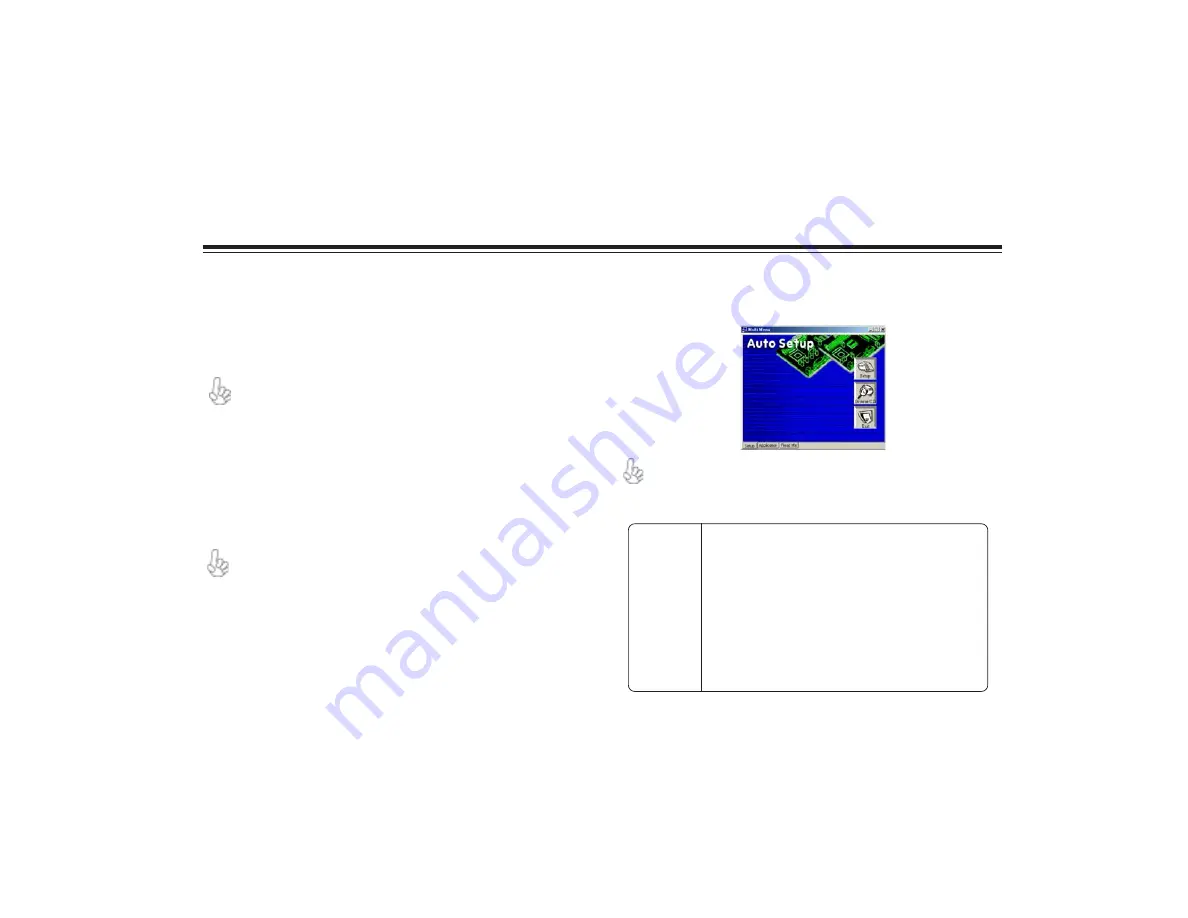
The support software CD-ROM disc loads automatically under Windows 98/ME/
2000/XP. When you insert the CD-ROM disc in the CD-ROM drive, the autorun
feature will automatically bring up the install screen. The screen has three buttons
on it, Setup, Browse CD and Exit.

If the opening screen does not appear; double-click the file “setup.exe” in
the root directory.

Setup Tab

Setup

Click the 

Setup

 button to run the software installation program. Select from

the menu which software you want to install.

Browse CD

The 

Browse CD

 button is the standard Windows command that allows you

to open Windows Explorer and show the contents of the support CD.
Before installing the software from Windows Explorer, look for a file named
README.TXT, INSTALL.TXT or something similar. This file may contain
important information to help you install the software correctly.
Some software is installed in separate folders for different operating
systems, such as DOS, WIN NT, or WIn98/95. Always go to the correct
folder for the kind of OS you are using.
To install the software, execute a file named SETUP.EXE or
INSTALL.EXE by double-clicking the file and then following the
instructions on the screen.

Exit

The Exit button closes the Auto Setup window.

Summary of Contents for 661FX-M Deluxe

Page 1: ...sed in this manual are the properties of their respective owners and are acknowledged FederalCommunicationsCommission FCC This equipment has been tested and found to comply with the limits for a Class...

Page 2: ...d including interference that may cause undesired operation CanadianDepartmentofCommunications This class B digital apparatus meets all requirements of the Canadian Interference causing Equipment Regu...

Page 3: ...lingtheMotherboard 5 SafetyPrecautions 5 ChoosingaComputerCase 5 InstallingtheMotherboardinaCase 5 CheckingJumperSettings 6 Setting Jumpers 6 Checking Jumper Settings 6 Jumper Settings 7 ConnectingCas...

Page 4: ...ting Setup 17 Updating the BIOS 18 UsingBIOS 19 Standard CMOS Features 19 Advanced BIOS Features 20 Advanced Chipset Setup 23 Integrated Peripherals 25 Power Management Setup 28 PNP PCI Configurations...

Page 5: ...ter 4 35 UsingtheMotherboardSoftware 35 AbouttheSoftwareCD ROM 35 Auto installingunderWindows98 ME 2000 XP 35 Running Setup 36 ManualInstallation 37 UtilitySoftwareReference 37 Multi LanguageTranslati...

Page 6: ...rator supports Ultra AGPIITM up to 2 7GB s bandwidth SiS964 964L supports Hi Precision Event Timer HPET for Microsoft Windows with multiple DMA bus architecture that supports isochroous re quest and c...

Page 7: ...idth Built in CRT FIFOs to support ultra high resolution graphics modes and reduce CPU wait state Supports auto clock throttling for 2D engine 3D engine SiS 964 964L SB Concurrent servicing of all DMA...

Page 8: ...four IDE devices One floppy disk drive interface Two 7 pin SATA connector A Communications Networking Riser CNR slot The 661FX M Deluxe motherboard supports Ultra DMA bus mastering with transfer rate...

Page 9: ...onnector for case front panel switches and LED indicators 9 SATA1 SATA2 Serial ATA connectors 10 JP3 BIOS Protect jumper 11 SPK1 Speaker header 12 JP1 Clear CMOS jumper 13 USB3 USB4 Front Panel USB he...

Page 10: ...ne or two floppy diskette drives and four enchanced IDE drives Make sure that your case has sufficient power and space for all drives that you intend to install Most cases have a choice of I O templat...

Page 11: ...d When setting the jumpers ensure that the jumper caps are placed on the correct pins The illustrations show a 2 pin jumper When the jumper cap is placed on both pins the jumper is SHORT If you remove...

Page 12: ...LEDs to the PANEL1 5 Connect the standard power supply connector to ATX1 6 Connect the auxiliary case power supply connector to ATX2 JP3 3 pin BIOS PROTECT JP1 Clear CMOS jumper This jumper is to cle...

Page 13: ...2V Power 12V 3 Sense Sensor Pin Signal Name Pin Signal Name 1 3 3V 11 3 3V 2 3 3V 12 12V 3 Ground 13 Ground 4 5V 14 PS ON 5 Ground 15 Ground 6 5V 16 Ground 7 Ground 17 Ground 8 PWRGD 18 5V 9 5VSB 19 5...

Page 14: ...ignal InstallingHardware Installing the Processor Caution When installing a CPU heatsink and cooling fan make sure that you DO NOT scratch the motherboard or any of the surface mount resistors with th...

Page 15: ...tes and heat dissipation we suggest that you use a high quality fan with 4800 rpm at least CPU fan and heatsink installation procedures may vary with the type of CPU fan heatsink supplied The form and...

Page 16: ...to install IDE devices such as a hard disk drive and a CD ROM drive About IDE Devices Your motherboard has a primary and secondary IDE channel interface IDE1 and IDE2 An IDE ribbon cable supporting tw...

Page 17: ...ology Attachment is the standard interface for the IDE hard drives which are currently used in most PCs These connectors are well designed and will only fit in one orientation Locate the SATA connecto...

Page 18: ...nding to the slot you are going to use 2 Install the edge connector of the add on card into the expansion slot Ensure that the edge connector is correctly seated in the slot 3 Secure the metal bracket...

Page 19: ...ne and line out ports for easier access SPDIFO1 SPDIF out header This is an optional header that provides an S PDIF Sony Philips Digital Interface output to digital multimedia device through optical f...

Page 20: ...9 Key Nopin 10 USB_FP_OC0 Over currentsignal Pin Signal Name Pin Signal Name 1 Ground 2 TX 3 TX 4 Ground 5 RX 6 RX 7 Ground Connecting I O Devices The backplane of the motherboard has the following I...

Page 21: ...16 InstallingtheMotherboard Memo...

Page 22: ...gement features The settings made in the Setup Utility affect how the computer performs Before using the Setup Utility ensure that you understand the Setup Utility options This chapter provides explan...

Page 23: ...therboard has an item called Firmware Write Protect in Advanced BIOS features disable it Firmware Write Protect prevents BIOS from being overwritten 3 Create a bootable system disk Refer to Windows on...

Page 24: ...osed in parenthesis Submenu items are denoted by a triangle f f f f f Standard CMOS Features This option displays basic information about your system Date and Time The Date and Time items show the cur...

Page 25: ...Leave this value at Auto and the system will automatically decide the fastest way to access the hard disk drive Drive A Drive B 1 44M 3 5 in None These items define the characteristics of any diskette...

Page 26: ...vel 2 L2 cache memory to improve performance Leave this item at the default value for better performance Hyper Threading Technology Enabled This item is only available when the chipset supports Hyper...

Page 27: ...a held down key Typematic Delay Msec Use this item to define how many millisec onds must elapse before a held down key begins generating repeat characters Security Option Setup If you have installed p...

Page 28: ...nables you to select the CAS latency time in HCLKs of 2 2 5 or 3 The value is set at the factory depending on the DRAM installed Do not change the values in this field unless you change specifications...

Page 29: ...RAM can be allocated to AGP for video purposes The aperture is a portion of the PCI memory address range dedicated to graphics memory address space Host cycles that hit the aperture range are forward...

Page 30: ...se items to enable or disable the internal PCI IDE channels that are integrated on the motherboard IDE Primary Secondary Master Slave PIO Auto Each IDE channel supports a master device and a slave dev...

Page 31: ...s to work including UltraDMA modes you will have to enable DMA transfer via the OS DE DMA Transfer Access Enabled This item allows you to enabled the transfer access of the IDE DMA IDE Burst Mode Enab...

Page 32: ...ial ATA mode Press Esc to return to the Integrated Peripherals screen fOnboard SuperIO Device Scroll to this item and press Enter to view the following screen Onboard FDC Controller Enabled This optio...

Page 33: ...umed by certain events Power Management Timeouts Power Management Timeouts Power Management Timeouts Power Management Timeouts Power Management Timeouts The power saving modes can be controlled by tim...

Page 34: ...ware power down that is controlled by the power button on your system If the item is set to Instant Off then the power button causes a software power down If the item is set to Delay 4 Sec then you ha...

Page 35: ...h Alarm and Time Alarm Upon arrival of the alarm time it will instruct the system to wake up When set to 0 zero for the day of the month the alarm will power on your system every day at the specified...

Page 36: ...o Plug and Play devices as they are required If you cannot get a legacy ISA Industry Standard Architecture expansion card to work properly you might be able to solve the problem by changing this item...

Page 37: ...Control By Auto This item allows you to set the CPU frequency Async AGP PCI SRC Clk Disabled This item allows you to set the yourAGP PCI SRC clock in asynchronous status CPU Frequency 100 This item al...

Page 38: ...and you can enter BIOS Setup freely PASSWORD DISABLED If you have selected System in Security Option of BIOS Features Setup menu you will be prompted for the password every time the system reboots or...

Page 39: ...34 34 34 34 34 Using BIOS Memo...

Page 40: ...xplorer Refer to the Utility Folder Installation Notes later in this chapter The support software CD ROM disc loads automatically under Windows 98 ME 2000 XP When you insert the CD ROM disc in the CD...

Page 41: ...ver lists will be different according to the motherboard you are installing The motherboard identification is located in the upper left hand corner 2 Click Next The following screen appears 3 Check th...

Page 42: ...ange at anytime without prior notice Please refer to the support CD for available software AWARD Flash Memory Utility This utility lets you erase the system BIOS stored on a Flash Memory chip on the m...

Reviews: