ECR International GreenMountain GMGS075E Installation, Operation & Maintenance Manual Download Page 15

15

GAS SUPPLY PIPING

CAUTION

WHAT TO DO IF YOU SMELL GAS
•  Do not try to light any appliance.
•  Do not touch any electrical switch; do not use 

any phone in your building.

•  Immediately call your gas supplier from a 

neighbor’s phone.  Follow gas supplier’s 

instructions. 

•  If you cannot reach your gas supplier, call the fire 

department.

!


General

• Use piping materials and joining methods acceptable 

to authority having jurisdiction.  In absence of such 

requirements National Fuel gas Code, ANSI Z223.1/

NFPA 54.

• Size and install gas piping system to provide sufficient 

gas supply to meet maximum input at not less than 

minimum supply pressure. See Tables 4a and 4b.

Table - 4a        Gas Pipe Sizes - Natural Gas

Length 

of Pipe 

- Ft.

Pipe  Capacity  -  BTU  Per  Hour  Input            

Includes Fittings

1/2"

3/4"

1"

1 -1/4"

20

92,000

190,000 350,000 625,000

40

63,000

130,000 245,000 445,000

60

50,000

105,000 195,000 365,000

Table - 4b        Gas Pipe Sizes - Propane Gas

Length 

of Pipe 

- Ft.

Pipe  Capacity  -  BTU  Per  Hour  Input            

Includes Fittings

5/8"

3/4"

1/2"

3/4"

20

131,000 216,000 189,000 393,000

40

90,000

145,000 129,000 267,000

60

72,000

121,000 103,000 217,000

* Outside diameter

Length of pipe or tubing should be measured from the gas meter 

or propane second stage regulator.

• Support piping with hooks straps, bands, brackets, 

hangers, or building structure components to prevent or 

dampen excessive vibrations and prevent strain on gas 

connection.  Gas valve will not support piping weight.

• Use thread (joint) compound (pipe dope) suitable for 

natural and liquefied petroleum gas.

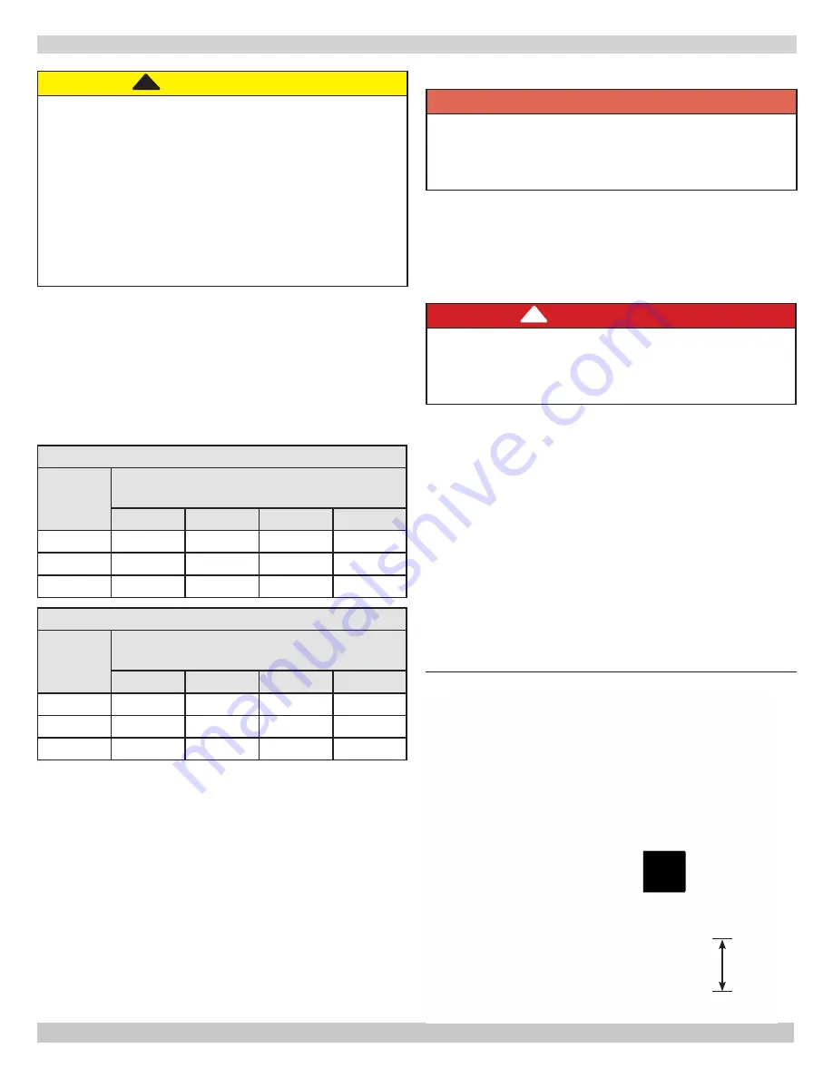
• Install field sourced manual main shutoff valve, ground 

joint union, and sediment trap upstream of gas valve. 

See Figure 11.

DANGER

Fire Hazard.  Do not use matches, candles, open 

flames, or other methods providing ignition source. 

Failure to comply will result in death or serious 

injury.

!


Leak Check Gas Piping

Pressure test boiler and gas connection before placing 

boiler in operation. Avoid excessive pressure that could 

damage pressure regulators, valves, or meters.

• Pressure test at 1/2 psig (3.5 kPa) or less.  Isolate 

boiler from gas supply system by closing manual gas 

shutoff valve. 

• Locate leakage using gas detector, noncorrosive 

detection fluid, or other leak detection method 

acceptable to authority having jurisdiction.  Do not 

use matches, candles, open flames, or other methods 

providing ignition source.

• Correct leaks immediately and retest.

Figure 11 - Gas Piping At Boiler

Propane Installation

 WARNING

Fire, explosion, asphyxiation hazard. Verify boiler 

is equipped with propane gas orifices and gas valve 

is configured for propane. Failure to follow these 

instructions may result in serious injury or death.

• Connections by licensed propane dealer only.
• Use two stage regulator provided by propane 

supplier.

• Have propane supplier check piping.

Summary of Contents for GreenMountain GMGS075E

Page 1: ...Steam Gas Fired Boilers INSTALLATION OPERATION MAINTENANCE MANUAL Models GMGS075E GMGS225E GMGS112E GMGS262E GMGS150E GMGS299E GMGS187E Manufactured by ECR International Inc 2201 Dwyer Avenue Utica N...

Page 2: ...1 Dimensions Inches Intermittent Ignition w Vent Damper Flue Diameter A Width GMGS075E 5 11 GMGS112E 6 14 GMGS150E 6 17 GMGS187E 7 21 GMGS225E 7 24 GMGS262E 7 27 GMGS299E 7 30 Add 5 to height for Ven...

Page 3: ...GMGS299E 9 Natural Gas 299 245 82 0 184 767 MBH 1 000 Btuh Btuh British Thermal Unit Per Hour For altitudes above 2 000 ft reduce input rate 4 for each 1 000 ft above sea level Heating Capacity is ba...

Page 4: ...whatsoever Introduction Boiler is designed for use in closed heating systems where all steam is returned as condensate and make up water is minimal Boiler is not designed for or intended for use in o...

Page 5: ...any other gas appliance with improper methods or materials could result in death or serious injury due to fire or to asphyxiation from poisonous gases such as carbon monoxide which is odorless and in...

Page 6: ...conditions of use Boiler location should not interfere with proper circulation of air Introduce outside air if normal infiltration does not provide necessary air Fresh Air for Combustion on page 11 6...

Page 7: ...or place any obstruction in discharge line Terminate freely to atmosphere where any discharge will be clearly visible and at no risk of freezing Allow complete drainage of valve and discharge line Ins...

Page 8: ...from the header one for each main 6 All boilers in gravity return systems must be equipped with a Hartford Loop as shown in Figure 5 7 When piping the vertical risers from the boiler to the header th...

Page 9: ...9 Figure 4 Recommended Near Boiler Piping Using One Supply Tapping SYSTEM PIPING...

Page 10: ...LATION SYSTEM PIPING Figure 6 Chilled Water Piping VALVES A B OPEN FOR HEATING CLOSE FOR COOLING VALVES C D CLOSE FOR HEATING OPEN FOR COOLING Figure 5 Recommended Near Boiler Piping Using Two Supply...

Page 11: ...ter than 0 60 Room volume is greater than 21 cubic feet divided by ACH air changes per hour x Total Input Mbh C Refer to National Fuel Gas Code for opening requirements between connected indoor spaces...

Page 12: ...uld not be longer than 3 4 the chimney height HT Figure 7 page 13 Vent Pipe Fasten sections of vent pipe with 3 sheet metal screws at each joint to make piping rigid Support horizontal portions of ven...

Page 13: ...er gas burning appliance to their previous conditions of use 7 Any improper operation of the common venting system should be corrected so the installation conforms with the National Fuel Gas Code ANSI...

Page 14: ...on and for vent damper troubleshooting guide refer to manual packaged with vent damper Horizontal Installation To Boiler Vent Damper To Chimney NO NO YES YES Flow Install vent damper with actuator to...

Page 15: ...or dampen excessive vibrations and prevent strain on gas connection Gas valve will not support piping weight Use thread joint compound pipe dope suitable for natural and liquefied petroleum gas Insta...

Page 16: ...ut off two wires are black One wire is located on secondary of 24 volt transformer second wire is located on pressure limit control F Boilers with PS 802 probe type low water cut off one wire is green...

Page 17: ...ol knob slightly and turn clockwise to OFF Do not force For Your Safety Read Before Operating WARNING If you do not follow these instructions exactly a fire or explosion may result causing property da...

Page 18: ...wn on left side of boiler Determine water level when boiler is off and cold when all water in the system is inside the boiler and return piping below water line and everything above water line is air...

Page 19: ...inner cones in softer blue outer mantel with no yellow Remain still when observing main burner flames Check main burner orifices burner throat and flame ports for dust and lint obstruction if flame ap...

Page 20: ...ower on and turn thermostat to call for heat C Gas valve opens for approximately 10 seconds time delay on probe type LWCO gas valve will close and red indicator illuminates on LWCO D When water is res...

Page 21: ...ild up Run connection from boiler drain valve to safe discharge point outside Shut off gas burners open drain valve allow all of water in boiler to drain out Close drain valve Allow boiler to cool slo...

Page 22: ...bead of 400 F RTV silicone to four mounting surface flanges of flue collector Mount flue collector on heat exchanger Tighten nuts and bolts 6 Seal front edge and four corners of flue collector to hea...

Page 23: ...e joints Rollout switch blown Have your service technician check heat exchanger for blockage Chimney flue is blocked Spill switch contacts open requiring manual reset of spill switch Have your service...

Page 24: ...s appliance must be replaced it must be replaced with type 105 C Thermoplastic wire or its equivalent Figure 13 Wiring Diagrams For Boilers With PS 802 Probe Type Low Water Cut Off Shown PS802 PS802 C...

Page 25: ...ny of the original wire as supplied with this appliance must be replaced it must be replaced with type 105 C Thermoplastic wire or its equivalent Figure 17 Wiring Diagrams For Boilers With 67D 1 Float...

Page 26: ...l Model WF 2U 24 water feeder maybe used with either of the low water cutoffs listed Water feeder maintains safe minimum water level Keeps boiler running by compensating for minor evaporative steam le...

Page 27: ...27 REPAIR PARTS...

Page 28: ...28 REPAIR PARTS...

Page 29: ...29 REPAIR PARTS...

Page 30: ...30 REPAIR PARTS Safety Relief Valve 14 11 NPT X 4 Nipple PF 033 02...

Page 31: ...31 Date Service Performed Company Name Tech Initials Company Address Phone...

Page 32: ...Manufactured by ECR International Inc 2201 Dwyer Avenue Utica NY 13501 web site www ecrinternational com...

Reviews: