Econ ELSA130 Installation And Operation Manual Download Page 1

Installation & Operation Manual


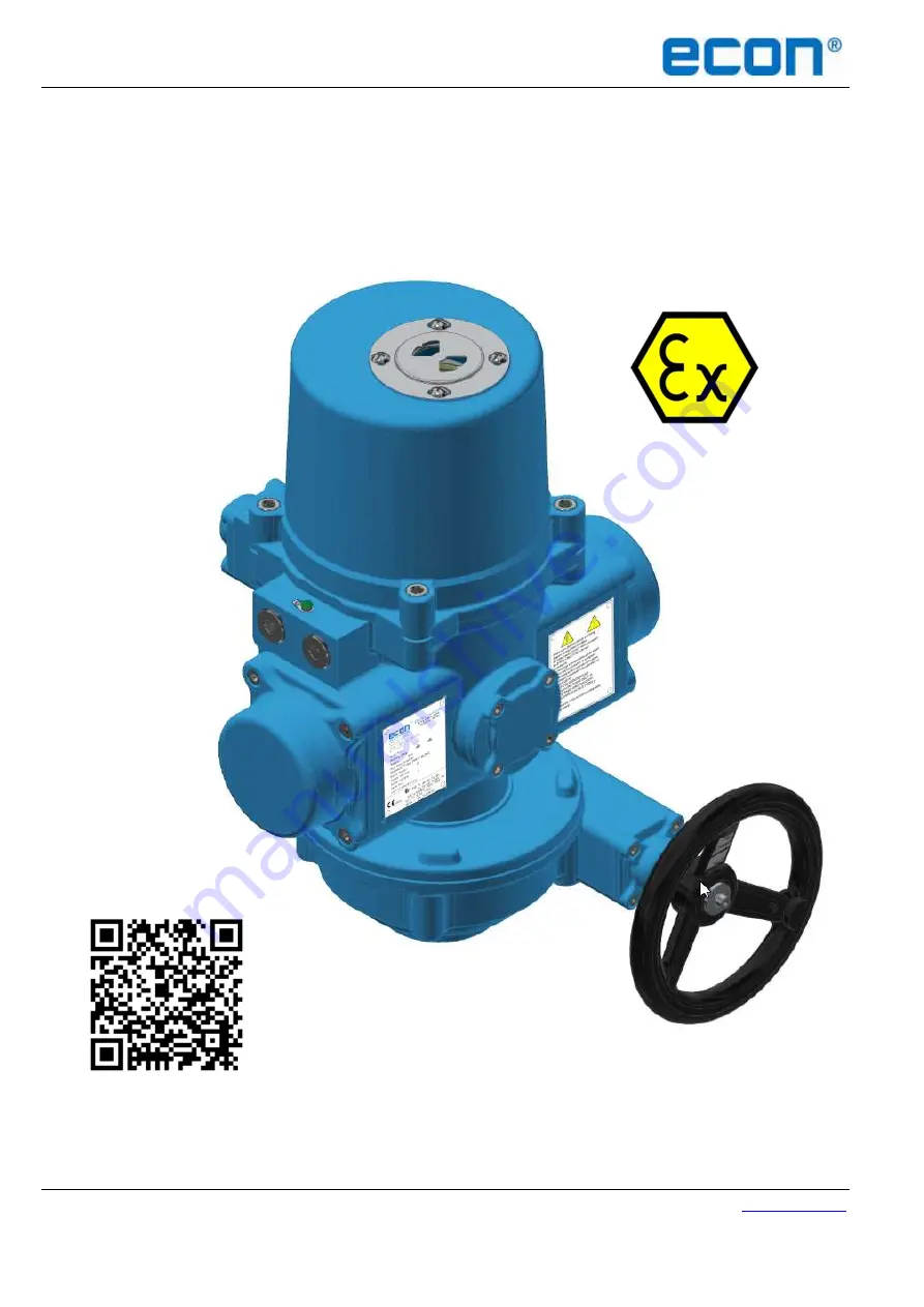
ECON actuator Fig. 7917EX, type ELSA50 – 260 


www.eriks.com


Rev. 0 – April 10

th

, 2019


ECON SPRING RETURN ELECTRIC ACTUATOR 

Fig. 7917EX,  type ELSA50 - 260


Installation and Operation Manual for actuator type: ELSA50, 130, 200 & 260


Summary of Contents for ELSA130

Page 1: ...n Manual ECON actuator Fig 7917EX type ELSA50 260 www eriks com Rev 0 April 10th 2019 ECON SPRING RETURN ELECTRIC ACTUATOR Fig 7917EX type ELSA50 260 Installation and Operation Manual for actuator typ...

Page 2: ...ator Selection 8 3 5 Sizing 9 3 6 Duty Cycle IEC 9 3 7 Flame path Joint 9 4 Mounting And Setup 11 4 1 Handwheel Installation 11 4 2 Valve Mounting Instructions 11 4 3 Wiring Instructions 13 4 4 Actuat...

Page 3: ...rce on the handwheel for operating as this can damage the actuator or valve 1 2 1 General The spring return actuator is shipped in spring return position spring unloaded Standard actuators will be sup...

Page 4: ...ase refer to section 1 2 3 To avoid functional failure caused by a static load do not touch any components on the PCB with metal tools or bare hands Use proper cable glands in order to seal the condui...

Page 5: ...ure of 105 C 221 F Working Conditions ATEX IECEx Atmospheric pressure 80 110 kPa Ambient temperature 30 C to 70 C 22 F to 158 F Relative humidity Not more than 95 25 C 77 F The actuator can operate no...

Page 6: ...ed in a dry area with a relative humidity of less than 90 20 5 C and at a temperature between 20 C to 40 C 4 F to 104 F The product shall be stored with suitable protection from corrosive substances w...

Page 7: ...ring stroke to reduce the water hammer effects in pipes A clutch less manual override is provided for manual positioning of the controlled device Actuators without a manual override can be ordered as...

Page 8: ...erial Number Date of manufacture ATEX and IECEx markings ATEX and IECEx certificate No Please make sure the explosion proof specification for the product is in consistence with nameplate and instructi...

Page 9: ...ls 3 4 Actuator Selection Model Mounting Flange Shaft A Depth of Shaft B ISO 5211 mm inch mm inch ELSA50 F07 17 0 669 30 1 181 ELSA130 F10 22 0 866 41 1 614 ELSA200 F12 27 1 063 45 1 772 ELSA260 F12 2...

Page 10: ...e running time and resting time It is calculated as below Duty Cycle x 100 Rest Time s If the motor running time is 10 s the spring return time is 5 s and the duty cycle is 50 the rest off time shall...

Page 11: ...as it will damage the closing surfaces Cover Installation Please ensure that the O ring seal is in good condition prior to cover installation Slowly re install the cover while being careful not to pi...

Page 12: ...9 11 4 Mounting And Setup 4 1 Handwheel Installation a Slide the fixing screw through the washers and handwheel and secure them to the override shaft as shown in the figure below Turn off power when i...

Page 13: ...it ensure that they are properly secured together by fastening all fasteners by using corrects tools f Remove the conduit entry plug to relieve the pressure inside the actuator for the ease of the top...

Page 14: ...lugs to reach the explosion proof function Please refer to section 1 2 2 4 4 Actuator Set up If the actuator is equipped with a manual override rotate the handwheel to return the actuator to its fully...

Page 15: ...e End Stop using a 10mm hex wrench to adjust the end position c Turn the buffer or End Stop in order to adjust the fully closed stop point ELSA50 One turn 2 3 degrees ELSA130 to ELSA260 One turn 1 4 d...

Page 16: ...g angle turn the cam clockwise To decrease the opening angle turn the cam counter clockwise ELSA50 ELSA130 up to ELSA260 d After adjusting the cam apply power to drive the actuator to the fully open p...

Page 17: ...nt ELSA50 One turn 2 3 degrees ELSA130 to ELSA260 One turn 1 4 degrees d Once completed tighten the hex nut replace cover and tighten the bolts If the buffer or End Stop is adjusted TC2 must be reset...

Page 18: ...losed position If it is in correct position turn the power supply off and lock the cap bolt of cam TC1 If it is not in the correct position repeat step C until the correct position is reached f If aux...

Page 19: ...y closed stop point Once the spring mechanism has been released when power outage the actuator will not drive under power again until it has reached its fail stop position and TC2 trips TC1 OPEN Clock...

Page 20: ...ease follow the steps below if an adjustment of these settings are required Please restart the actuator after adjusting 1 2 3 4 5 6 7 8 Factory Setting ON OFF OFF ON OFF OFF OFF ON 4 20 mA input ON OF...

Page 21: ...tch 6 is used to set the corresponding relationship between value of signal input and operation direction of actuator When S6 is set to ON The program defines 20 mA or 5 V or 10 V as a command for ful...

Page 22: ...When S6 is set to OFF The program defines 20 mA 5 V 10 V as a command for fully open positioning The line graph below shows the signal level and the corresponding position of the actuator When a high...

Page 23: ...ch Setting SW2 Original factory setting is 3 When switched to 1 The Highest Sensitivity is activated and the 0 90 degree travel is divided up to around 80 movements When switched to 0 The Lowest Sensi...

Page 24: ...fully open setting is completed Fully CLOSED setting a Press and hold the DOWN switch to operate the actuator to close until it has reached fully closed position and LD1 lights Then put in a signal of...

Page 25: ...LD5 lights b Input a voltage exceeding the rated For example preset with 2 10 V input but input 13 5V Verify if the switch 1 is set in accordance with the type of input signal Please refer to section...

Page 26: ...rates too frequently and exceeded duty cycle rating b A torque overload caused by the valve c Supply voltage was too high or too low out the tolerance of deviation d Wrong power supply a Adjust the sy...

Page 27: ...but not modulating Possible problems Solution The signal input with a reversed polarity it means a signal failure Verify if the negative pole of signal input connected to terminal 6 and the positive...

Page 28: ...riginal factory setting Fail clockwise CW rotation When energized the driven valve rotates CCW viewed from the top of the actuator Meanwhile the springs are compressed On loss of power the spring retu...

Page 29: ...ft Rotate the indicator 90 degrees and lock the screws then re install the indicator scale Figure 2 The tag of CLOSE direction with an arrow pointing on the handwheel is printed on both of the sides A...

Page 30: ...260 www eriks com Rev 0 April 10th 2019 29 If you have questions about this product Please contact the nearest ECON distributor You can find them on www eriks com ERIKS Flow Control Cypresbaan 63 290...

Reviews: