Ecoflam BLU TS 3000.1 PR HT Manual Download Page 23

The list of faults/causes/possible solutions for a set of main failures is a guideline for professional personell authorised to carry out
service and maintenance. 
Irregular burner operation or malfunction: check that every adjustment parameter is correctly set as per instruction on this manual.

TROUBLESHOOTING INSTRUCTIONS

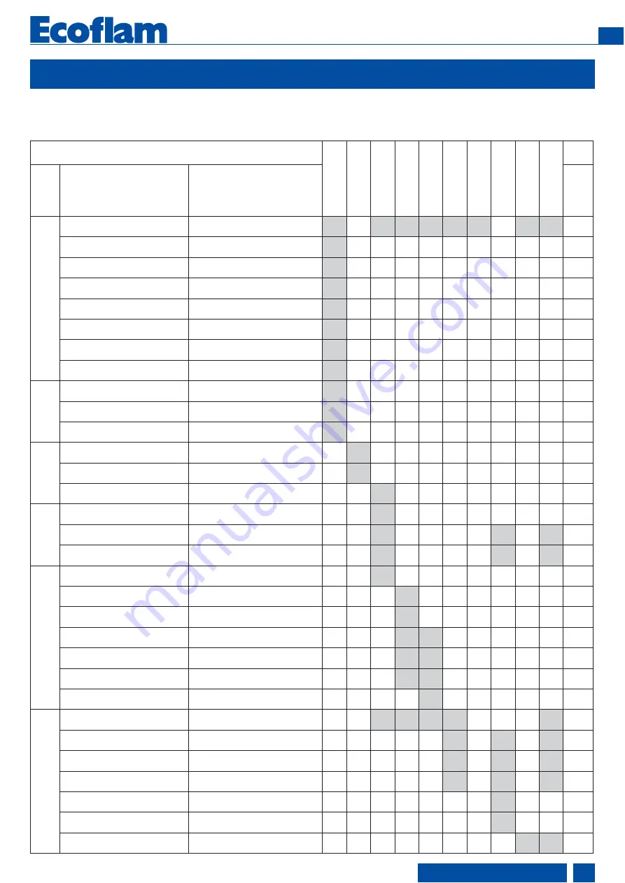
TROUBLESHOOTING TABLE

GAS OPERATION

Burner doesn't start

Burner starts with continuous pre-purge

Burner starts and then goes into lock- out

Pilot Ignition failure  (1st safety time)

Main Ignition failure  (2nd safety time)

Burner lock-out after flame appereance / pulsation

Flame control repeats the cycle and does not give consent

Combustion emission not satisfactory

Burner doesn't switch into Hi flame

Burner lock-out during operation

LFL

ST

A

TUS

CAUSES 

REMEDIES

MUL

TICALOR

MUL

TIFLAM

BLU

PRE-ST

AR

T


(MISSING SIGNALS)

Defective control box unit

Replace control box unit

X

X

X

X

X

X

X

X

YES

No electrical power supply

Wrong electrical connections

Check switches/contactors

Check connections

X

YES

Air pressure switch not "closed"

Check contacts

X

YES

Boiler thermostats open

Check contacts

X

YES

Fan motor overload intervention

Replace Fuse

X

YES

Auxiliaries fuses interrupted

Replace Fuse

X

YES

Servomotor [CLOSE] position 

switch not reach

Check servomotor settings

X

YES

Minimum gas pressure swtich 

not close

Open manual ball valve, check 

pressure switch settings, contacts, 

replace if necessary

X

YES

LEAKAGE

CHECK

Leakage test successful - 

signals not arrive to control unit

Check contacts

X

YES

Leakage Test failure (VPS / VDK)

Clean valves or replace leakage

controller if necessary

X

YES

Leakage Test failure (LDU kit)

Check contacts, clean valves or 

replace leakage controller if necessary

X

YES

SEQUENCE 

ST

AR

T

Servomotor [OPEN] position 

switch not reach

Check servomotor settings

X

YES

Servomotor [MIN] position 

switch not reach

Check servomotor settings

X

YES

Extraneous light

Eliminate light source

X

YES

LACK 

OF AIR

Air pressure switch fail to connect 

to Terminal 14

Check contacts

X

YES

Fan contaminated / dirty

Clean fan 

X

X

X

YES

Fan motor rotation direction 

not correct

Check direction and contactor

X

X

X

YES

IGNITION & FLAME 

ST

ABLISA

TION PERIOD

Flame supervision circuit internal 

test failed

Replace control unit

X

YES

Pilot flame failure - Pilot gas valves

not open

Check valves contacts / replace if

necessary

X

YES

Pilot flame establish - weak flame

signal

Check Ionisation or flame sensor

Replace if necessary

X

YES

Ignition transformer faulty

Replace

X

X

YES

Ignition cable & electrodes defective

Replace

X

X

YES

Electrode bad position

Check setting / replace if necessary 

X

X

YES

Main solenoid valve fails to open

Check contacts and clean valves

Replace valves if necessary

X

YES

COMBUSTION

Flame sensor signal failure

Clean, re-position or replace if

necessary

X

X

X

X

X

YES

Head adjustment not correct

Check settings

X

X

X

YES

Gas / Air mixture setting not correct

Check settings

X

X

X

YES

Oscillating gas pressure

Install damping throttle (AGA 25) - 

order separately or reduce suppply

pressure

X

X

X

YES

Capacity reduction due to lower 

gas supply pressure

Check gas pressure, clean filter, 

replace cartridge if necessary

X

YES

Gas pressure regulator 

not regulating

Replace regulating valve

X

YES

Load control device does not close

Check load control, 

replace if necessary

X

X

YES

420010487501

EN

www.ecoflam-burners.com

23

Summary of Contents for BLU TS 3000.1 PR HT

Page 1: ...GAS BURNERS EN BLU TS 3000 1 PR HT BLU TS 4000 1 PR HT Gas train manual is separate www ecoflam burners com BLU TS 3000 1 PR TC SGT HT 230 50 3143084 BLU TS 3000 1 PR TL SGT HT 230 50 BLU TS 4000 1 P...

Page 2: ...Head loss diagram 13 Pressure loss diagrams 14 Electrical connections 16 Start up checking procedure 17 Exhaust gas test 18 Start up 19 Adjusting the max air flow rate 19 Firing head setting 19 Servo...

Page 3: ...ral EN676 directives and guidelines must be observed EN676 compulsory kit and accessories in order to comply to the safety regulations Additional accessories and kits shall be installed by the install...

Page 4: ...gulations For burners over 1700 kW gas train connection pipe must be ordered Kits and accessories are managed and delivered separately Component type BBCH Burner Body with Combustion Head without gas...

Page 5: ...ixing flange 9 Air flap regulation 12 Lifting eyebolts 13 Mechanical cam gas 15 Servomotor for gas and air 16 Gas train 19 Gas filter 20 Ball valve 23 Antivibration coupling 24 Tightness control GTCP...

Page 6: ...TRAIN INTO THE BURNER AND CALCULATE THE OVERALL DIMENSIONS refer to the dimension page and thE gas train manual for all detailed information Gas governor Filter FGDR FILTER Compulsory EN676 Tightness...

Page 7: ...kcal Nm3 G30 L C V 29 320 kcal Nm3 Emission class std Standard Class 2 GAS EN676 120 mg kWh Control unit Type LFL LGK Gas train GT VGD separate gas train Filter KIT Tightness control Other KIT ACS Gas...

Page 8: ...the boiler backpressure Example Burner thermal output 8000 kW L flame m 5 m medium value D flame m 1 m medium value WARNING Some flame modifications can be done in our FLEXSHOP in the factory in orde...

Page 9: ...der to be able to extract it during maintenance Burner boiler mounting flange Packaging only burner WARNING Please follow the suggested dimension for the hole on the boiler flange in order to fit the...

Page 10: ...m will vary the positions of the gas control valve and air damper and thus regulate the gas flow rate in a linked concept with the air flow rate The burner can either be controlled by a 2 stage slidin...

Page 11: ...be and the boiler lining must be sealed with appropriate insulating material BURNER LINING Check before burner installation 1 Depending on the type of boiler reverse flame or three pass check the burn...

Page 12: ...es the result of the leak test must be duly certified VENTING Prior to taking the burner into operation or after any repair work make sure to vent the complete gas feed line and the gas valves and ins...

Page 13: ...ording to the instructions of the gas train separate manual KITPRES Maximum pressure switch assembly Maximum pressure switch is provided as a kit and shall be assembled into the main gas train accordi...

Page 14: ...LU 3000 1 PR MULTICALOR 300 1 MULTIFLAM 300 1 VGD 40 100 no neutral 20 700 1C FILTER DN 100 22 700 VGD 40 080 no neutral 30 700 FILTER DN 80 35 700 VGD 40 065 no neutral 45 700 FILTER DN 65 55 700 VGD...

Page 15: ...Inlet gas pressure MIN mbar Inlet gas pressure MAX mbar Diagram BLU 4000 1 PR MULTICALOR 400 1 MULTIFLAM 400 1 VGD 40 100 no neutral 27 700 2C FILTER DN 100 30 700 VGD 40 080 no neutral 40 700 FILTER...

Page 16: ...be checked by qualifed personnel The manufacturer declines all responsibility for modifcations or connections different from those shown in the electrical scheme Adapters multiple plugs and extension...

Page 17: ...be available the exhaust gas duct up to the measuring point must be free of leaks to prevent anomalies in the measurement results GAS START UP Connect the measuring instruments for the gas head pressu...

Page 18: ...to be exceeded DETERMINING THE VOLUMETRIC GAS FLOW RATE The thermal furnace output of a boiler QF is the amount of heat supplied with the gas in a unit of time When taking the burner into operation t...

Page 19: ...ut the adjusting Firing head setting Servomotor SQM50 Air damper motor pre setting The cams of the servomotor are set from the factory in order to start the burner and reach the maximum output The fol...

Page 20: ...the adjustment value of the air pressure switch until to have the burner lockout Remove the obstruction from the air intake screw on the cover C and start the burner by pressing the control box rearm...

Page 21: ...with air periodically replace it if necessary After the cleaning of the components of the gas train perform the leakage test Make visual inspection of the burner s electrical components and eliminate...

Page 22: ...duction in the ionization current and cause a safety shut off of the burner due to a flame detection failure In this case check the position of the electrode its electric connection and the earthing o...

Page 23: ...age controller if necessary X YES Leakage Test failure LDU kit Check contacts clean valves or replace leakage controller if necessary X YES SEQUENCE START Servomotor OPEN position switch not reach Che...

Page 24: ...not closed between terminals 12 and 4 or 4 and 5 or the contacts of all control and safety units in the controlled system are not closed e g gas pressure or air pressure switches temperature or pressu...

Page 25: ...he reversible actuator is fitted with a synchronous motor which drives a shaft via a gearbox The shaft end carries a coupling to drive the fuel and combustion air controlling element The SQM actuator...

Page 26: ...FICATION DESCRIPTION ECN MODIFICATION BLU TS 3000 1 4000 1 5000 1 6000 1 PR SGT QUADRO COMANDI A POZZOBON 28 03 2012 2 420110081300 1 A RIGONI LANDIS SQM 50 481A2 ER RBA12CB103 LANDIS LFL 1 333 1 622...

Page 27: ...E TERMICO MOTORE VENTILATORE FUSIBILE FILTRO ANTIDISTURBO INTERRUTTORE GENERALE CON FUSIBILE KMV HLB FMV FU FUSE Z Q ESPIA DE FUNCIONAMIENTO LAMPE DE FONCTIONNEMENT LAMPADA DI FUNZIONAMENTO HLF WORKIN...

Page 28: ...DI TENUTA YVGS YVG F 1 E D 2 3 4 C B A 1 2 3 4 5 6 7 8 F E D 5 6 7 C B 8 A 2 1 3 TOT SHEET SHEET DESIGNER DESCRIPTION DATE FIST CREATION CODE SIGNATURE R D DEPARTMENT CONTROLLER Ecoflam Bruciatori SE...

Page 29: ...ELETTROVALVOLA GAS SPGmin YVGS YVG YVG YVGS T P SPGmin T P SPGmin YVGS YVG NON UTILIZZATA VI CAMMA DI REGOLAZIONE ARIA BASSA FIAMMA LAVORO CAMMA REGOLAZIONE ARIA ACCENSIONE MINIMA POTENZA CAMMA REGOL...

Page 30: ...APPENDIX Spare parts list 420010487501 EN www ecoflam burners com 30 19 23 24 2 Blu TS 3000 1 4000 1 PR 1 20 3 4 8 7 10 9 16 11 13 14 15 17 12 21 5 6 22 25 18 26...

Page 31: ...ELECTRODE 65320891 65320891 10 IONIZATION PROBE 65320892 65320892 11 GAS PIPE TC 65321664 65321664 TL 12 ROD TC 65320242 65320242 TL 65320243 65320243 13 FIRING HEAD 65321666 65321666 14 DISC 65320742...

Page 32: ...ul to its products without affecting their main features Ecoflam Bruciatori S p A si riserva il diritto di apportare ai prodotti le modifiche che riterr necessarie o utili senza pregiudicarne le carat...

Reviews: