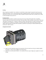
6. Verify all coils are connected at identical taps.
7. Torque the taps connections to the recommended values per Table 2, Section 7.5.
8. Remove the shorting connection on the HV and LV terminals.
9. Inspect the transformer to ensure that no tools or other objects have been left in the vicinity of the transformer
10. Replace all access panels, and re-energize the transformer
When cable connections are required, conductors suitable for at least 90
⁰
C should be used. Connections should be made
and supported such that they do not stress the terminals with the weight of the cables while still allowing for expansion
and contraction. The minimum electrical clearances to the core & coil per Table 1 in Section 7.4 should be maintained
and all connections should be torqued to the recommended values per Table 2 in Section 7.5.
Note: Top cable entry is not permitted in the main transformer compartment in accordance with CSA C22.2 No.47. If the
enclosure is fitted with air terminal chambers barriered off from the main compartment, then cables may be brought
into the top of these terminal chambers. Please contact Rex Power Magnetics or refer to the outline drawings supplied at
the order stage for instructions on appropriate cable entry locations.
Anti-vibration Pads
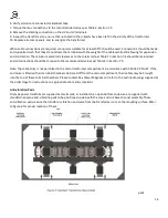
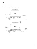
Dry type power transformers supplied as core & coils, or installed in an open bottom enclosure are supplied with
standard neoprene anti-vibration pads to be positioned underneath the core and coil base channel assembly. These
anti-vibration pads reduce the transfer or vibration and noise from the transformer core to the mounting surface. Refer
to figure 6 for proper location of these
pads.
16

