(12) On the MFD, scroll to the SETUP tab, press the SENSOR Soft Key. Set the ADC
PFD source selection from AUTO to ADC 2.
(13) On the IFR 6000, press the XPDR button once.
(14) Once XPDR - ALT ENCODER is displayed, press the SOURCE SELECT Soft Key
until SOURCE - XPDR is displayed. Press the RUN TEST Soft Key.
(15) Make sure that an altitude reported on IFR 6000 matches L PFD altitude indication
+/- 100 ft.
(16) On the MFD, set the ADC source back to AUTO.
(17) Set the WOW Box Switches to W-on-W (on-ground).
(18) Set D-XPDR 2 to STANDBY MODE.
D. Diversity Transponder-2 MODE A,C,S Test using Transponder Test Set (IFR 6000)
(Lower Antenna)
(1) Remove Antenna Clamp and Shield Assembly (part of Transponder Test Set IFR
6000) from lower transponder antenna (bottom of the center cabin/fuselage).
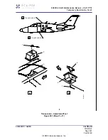
(2) Install Antenna Clamp and Shield Assembly (part of Transponder Test Set IFR 6000)
on upper transponder antenna (top of the center cabin/fuselage), in accordance with
instructions in IFR 6000 Ramp Test Set Operation Manual.
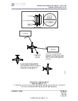
(3) Pre-position the Transponder Test Set IFR 6000 antenna to point at the aircraft’s
lower Transponder 2 antenna (bottom of the center cabin/fuselage).
(4) On the Transponder Test Set (IFR 6000) SETUP-XPDR page, use NEXT PARAM or
PREV PARAM softkeys to select each parameter, and the “arrow” DATA keys to set
the values listed below:
•
ANTENNA: BOTTOM
•
RF PORT: ANTENNA
•
ANT RANGE-TOP: 18 ft.
•
ANT HEIGHT-TOP: 7 ft.
•
ANT RANGE-BOTTOM: 18 ft.
•
ANT HEIGHT-BOTTOM: 1 ft.
•
DIR CABLE LOSS: Ignore
•
ANT CABLE: 1 ft.
•
ANT CABLE LOSS: As marked on blue cable (should be 0.1 dB)
•
ANT GAIN (dBi) - 1.03 GHz: As marked on test set antenna
•
ANT GAIN (dBi) - 1.09 GHz: As marked on test set antenna
•
UUT ADDRESS: AUTO
•
MANUAL AA: Ignore
•
DIVERSITY TEST: ON
•
PWR LIM: FAR 43
EA500 Aircraft Maintenance Manual — 06-117751
Temporary Revision No. 34-21
EFFECTIVITY: NOTED
34-50-20
CONFIG C
Page 534
Sep 30/20
© 2020 Eclipse Aerospace, Inc.


