background image

11

BrightFire 200, V1, Operating Instructions, Edition 09.15

Adjustment, Start
and Stop

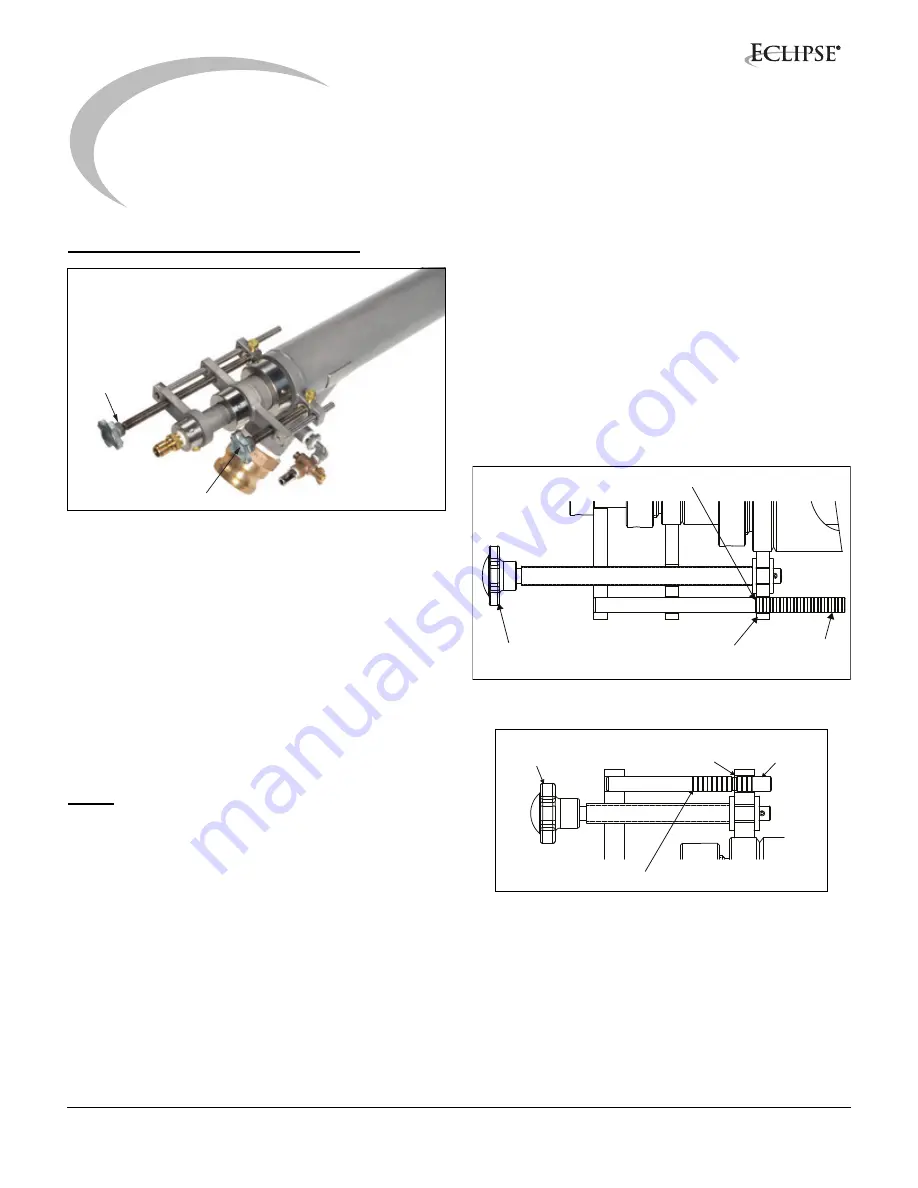
BrightFire 200 Flame Adjustments

Figure 2.1. BrightFire 200 Adjustments

The BrightFire

®

 200 has two adjustment valves, an area

adjustment (see Figure 2.1) and a flow adjustment. The
area adjustment (see Figure 2.2) changes the annulus
area between the inner and outer nozzles and is used to
control flame length. The flow adjustment (see Figure 2.3)
opens and closes an internal valve that changes the
distribution of gas flow between the outer and inner gas
tubes and is used to control where the heat from the flame
is released in the furnace. This can be changed
independently of the flame length. In addition, the firing
angle of the burner can be adjusted using the gimbal
mounting bracket adjustments to optimize gas flow into
the air stream. (Refer to Gimbal Bracket Info Guide 1113.)

NOTE:

 Mounting bracket adjustments should only be

done on the off-firing side to prevent natural gas from
deflecting back into the port area if the seal between the
socket plate and burner nozzle is lost.

To adjust the burners once the furnace is at, or near,
normal operating conditions, begin by adjusting the area
adjustment to set the flame to the desired length.
Increasing the annulus area by moving the adjustment
back (counter-clockwise rotation of the adjustment knob)
will lengthen the flame while moving the adjustment
forward (clockwise rotation of the adjustment knob) will
shorten the flame.

To read the indicator rod positions for the area and flow
adjustments, the first ring starting from the back of the
burner indicates position ‘1’. The position is indicated by
the ring that is flush with the back face of the adjusting lug.
Position 1 on the area adjustment rod indicates the inner
nozzle is all the way forward within the outer gas annulus,
flush with the face of the outer nozzle. Position 1 on the
flow adjustment rod indicates the inner flow valve is
closed with the maximum amount of gas flow through the
center jet. Refer to figures 2.2 and 2.3 which show an area
adjustment at position 1 and a flow adjustment at position
10.

Figure 2.2. Area Adjustment Mechanism

Figure 2.3. Flow Adjustment Mechanism

The flame is typically set about 2/3 of the width of the
furnace (length for end fired furnaces). The flame should
not impinge on the far wall or fire into the opposite side
port. Excessive lofting of the flame should also be avoided
to prevent damage to the furnace crown. Flames should
be above the glass or batch pile surface, and should not
be too low to prevent dust kick-up and batch carry-over
into the opposite port.

Area

Adjustment

Flow

Adjustment

Adjusting

Lead Screw

Position Indicator:

Read Markings Here

Position

Indicator

Position 1

Adjusting

Lead Screw

Position Indicator:

Read Markings Here

Position

Indicator

Position 1

4

Summary of Contents for BrightFire 200 series

Page 1: ...Eclipse BrightFire 200 Burners BRT Size G M and B Version 1 Operating Instructions Edition 09 15...

Page 2: ...and Eclipse will not be liable for any other injury loss damage or expenses whether direct or consequential including but not limited to loss of use income or damage to material arising in connection...

Page 3: ...l of Components 6 BrightFire 200 Adjustable Burners 7 Gimbal Mounting Bracket Installation 7 Pre Start Considerations 7 BrightFire 200 Installation and Start Up During Initial Heat Up Furnace 8 Bright...

Page 4: ...ncreased flame control and burner flexibility Lower NOX emissions Compatible with current mounting bracket for easy installation Compatible with current BrightFire gas and cool ing air connections for...

Page 5: ...er equipment installed under the furnace port Eclipse recommends installing a safety guard around moving parts Eclipse recommends considering any area with moving mechanical parts a restricted area Th...

Page 6: ...ks from UL FM CSA European EN 746 2 with CE mark from TuV Gastec Advantica Electrical Wiring All the electrical wiring must comply with all applicable local codes and or standards such as NFPA Standar...

Page 7: ...termined from the furnace and port information Gimbal Mounting Bracket Installation NOTE For additional info on the Gimbal Mounting Bracket refer to Info Guide 1113 1 Set all bracket adjustments to ze...

Page 8: ...main burners is increased the heat up burner input is decreased to maintain the heat up schedule until the heat up burner can be removed Figure 3 1 Typical Installation Under port Figure 3 2 Typical...

Page 9: ...ngement incorporates two burners per port Both burners of any given port should have equal gas flow and be adjusted in pairs when balancing gas flow On a typical under port fired furnace either side p...

Page 10: ...et the main gas flow control to manual and open to 10 15 7 Establish gas and cooling air supply up to the local shut off valves 8 Beginning with one burner on the off firing side of the furnace discon...

Page 11: ...tation of the adjustment knob will lengthen the flame while moving the adjustment forward clockwise rotation of the adjustment knob will shorten the flame To read the indicator rod positions for the a...

Page 12: ...ed further from the port opening while maintaining lower NOX emissions Converting BrightFire 200 from Gas to Oil Firing NOTE If firing heavy fuel oil the oil must be conditioned to maintain a viscosit...

Page 13: ...ate plugging of the regenerator ports instrumentation issues or furnace wear allowing infiltration of ambient air A side to side bias in the ratios may be required 5 Check the rear packing nuts to ver...

Page 14: ...and nut but do not tighten 20 Insert the inner gas tube through the rear of the burner until the end is flush with the area adjustment lug 21 Tighten the inner gas tube locking nut and the packing gla...

Page 15: ...illimeter mm inch in 3 94 x 10 2 MJ Nm Btu ft standard 26 86 From To Multiply By kiloPascals kPa millibar mbar 10 meter m millimeter mm 1000 millibar mbar kiloPascals kPa 0 1 millimeter mm meter m 0 0...

Page 16: ...Eclipse Inc All Rights Reserved...

Reviews: