background image

KGL Operating Manual – VS 3010 BS

2018-07-02

/

24 178

4.4 Low-pressure Regulation

The low-pressure regulation has the task of maintaining the suction side pressure at a specified setpoint. The 
controller provides two different methods for this regulation task:

Step controller
Regulation by loading and unloading compressor stages or compressor capacity stages
Combined control
Regulation using a speed-controlled compressor in combination with one or more fixed-speed 
compressors

The setting of the setpoints for the temperature ranges Z1 and Z2 is dependent on the room temperature or 
the refrigeration requirement (in conjunction with the E*LDS case controllers).

The actual value recording is performed using two 

 (one for each temperature 

pressure transducers, page 22

range) with continuous current output (4..20 mA) or voltage output (0..10 V).

4.4.1 Control algorithm for LP control

The control algorithm depends on the type of control.

In the wet vapour range, the temperature is a clear function of the pressure: t = f (p, refrigerant). The 
controller calculates temperatures for the LP range from the recorded pressures. Temperature values 
are used exclusively for the regulation. In the manual, temperatures (t /t ) represent pressures (p /p

0 c

0

c

).

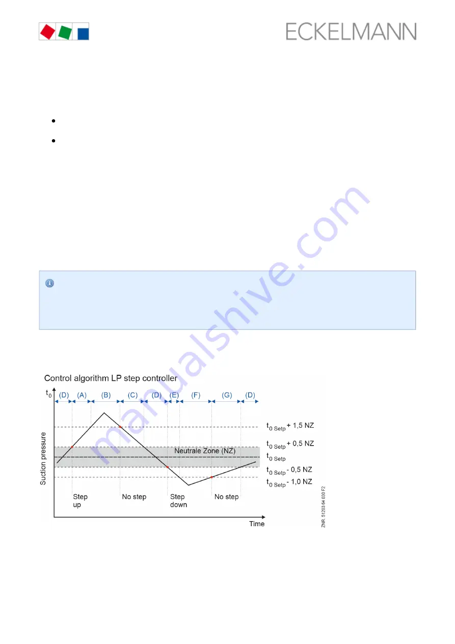
4.4.2 Control algorithm with LP step controller

The low-pressure measured by an A/D converter is compared with the setpoint: 

(A) At a pressure greater than the setpoint plus 0.5 times the neutral zone (NZ) and less than the setpoint plus 
1.5 times the NZ, the step switching mechanism loads stages in the event of a 

 pressure change.

positive

(B) At a pressure greater than the setpoint plus 1.5 times the NZ, the step switching mechanism loads stages 

 of the pressure change.

independently

(C) In the case of falling pressure that is less than the setpoint plus 1.5 times the NZ and is greater than the 

Summary of Contents for VS 3010 BS

Page 1: ...Operating instruction VS 3010 BS Pack Controller For booster satellite systems July 2018 1 02 Firmware V5 06 ...

Page 2: ...al and information such as data sheets more detailed documentation and FAQs are available for you on line in E EDP Eckelmann Electronic Documentation Platform at www eckelmann de elds You reach all relevant documents for this component directly using the QR code Information on safety and connection instructions are described in detail in chapter Industrial safety notes All rights to any use whatev...

Page 3: ...rithm with LP step controller 24 4 4 2 1 Neutral zone with compressor step control 25 4 4 2 2 Compressor control times for compressor step regulation 25 4 4 3 Control algorithm with LP combined control 26 4 4 3 1 Loading unloading of fixed speed compressors 26 4 4 3 2 Loading unloading of fixed speed compressors during operation with capacity controlled compressors 27 4 4 3 3 Compressor control ti...

Page 4: ...for tandem operation 58 4 6 1 9 Limiting the opening degree 58 4 6 1 10 Fixed opening degree for service purposes 59 4 6 1 11 Emergency Op 59 4 6 1 12 Manual Shutdown 59 4 6 1 13 Cascade disabling refrigeration points 59 4 6 1 14 Alarm due to implausible opening degree 60 4 6 2 Control of the cascade by a case controller 60 4 7 Heat recovery mode 60 4 7 1 Setpoint calculation in HR mode 61 4 8 Mon...

Page 5: ...sting is set to Cold rooms El UA 82 4 15 9 Error during discharge gas defrosting 82 5 VS 3010 BS Installation and start up 84 5 1 DIN rail mounting 84 5 2 Default hardware settings 84 5 2 1 SIOX extension module for DIN rail mounting 86 5 2 1 1 Connection of the SIOX modules to the pack controller 87 5 2 2 Default settings with S1 88 5 2 3 Setting the CAN bus address with S2 90 5 2 4 Setting of th...

Page 6: ...ing remote operation page 115 126 8 2 2 1 CI 4x00 System Centre Remote control 126 8 2 2 2 CI 3x00 store computer AL 300 operator terminal remote control 126 8 2 3 Cancelling entry block 127 8 2 3 1 CI 4x00 system centre login and logout 127 8 2 3 2 CI 3x00 store computer AL 300 operator terminal unlock 128 8 2 4 Activating service mode 128 8 2 4 1 CI 4x00 system centre service mode 128 8 2 4 2 CI...

Page 7: ...a VS 3010 BS SIOX 175 12 2 Mechanical Data VS 3010 177 12 3 Mechanical Data SIOX Extension Module With manual control switch 177 13 Part numbers and accessories VS 3010 BS 178 13 1 Pack controller VS 3010 BS SIOX extension module 178 13 2 Accessories for VS 3010 BS 178 ...

Page 8: ... V AC relay outputs no voltage is present The warning signs and symbols used for the safety instructions and hazard warnings in this documentation are described in detail on the following page 1 3 Warning Signs and Symbols Used Explanation of the warning signs and symbols used for the safety instructions and hazard warnings in this documentation Attention symbol general hazard warning Hazard warni...

Page 9: ...VS 3010 BS 2018 07 02 9 178 Failure to observe the attention symbol can result in personal injury in extreme cases serious injuries or death and or damage to property Voltage symbol warns about hazardous electrical voltage ...

Page 10: ...entire E LDS system the accident prevention regulations and general safety regulations must be strictly complied with Important information safety instructions and hazard warnings is indicated by appropriate symbols see chapter Follow these instructions in order to prevent accidents and danger to life Conventions page 8 and limb as well as damage to the E LDS system Warning about dangerous electri...

Page 11: ... enable transmission of alarms using a GSM modem via a mobile telephone system In standalone operation or as an alternative to monitoring with system centre operator terminal an available alarm contact on the controller must be used to realise transmission of alarms via a telephone network After the setting up of transmission of alarms or alarm signalling this must be tested and function checked f...

Page 12: ... in accordance with the scope of functions and in accordance with the environmental conditions described in this operating manual Start Note the safety instructions and the instructions for installation and start up operation and maintenance the commissioning and or operation of the machine system AFTERWARDS The safety and the function of the machine system are only fulfilled with this intended us...

Page 13: ... to as ESD below are labelled with the warning sign shown Electrostatic charges arise from friction of insulating materials e g floor covering items of clothing made of synthetic fibres etc Even small charges can result in damage to or destruction of components Damage cannot always be established directly but partially does not result in failure until after a certain operating time 1 4 5 1 ESD gui...

Page 14: ...lektrostatisch efährdete auelemente oder Baugruppen E G B ESD lectro tatic ischarge lectro ensitive evices E s d E S D VDE erband er lektrotechnik lektronik Informationstechnik e V V d E E IEC nternational lectric ommittee I E C BGV A3 m loyers Liability ssociation regulations for health and safety in the workplace E p A ...

Page 15: ...0 BS connection and terminal assignment page 105 VS 3010 BS Base Module Digital inputs 23 x input 230 V AC Relay outputs 6 x normally open contact 230 V AC 4 x changeover contact 230 V AC Manual control switch For manual override Analogue Inputs Outputs 2 x input Pt1000 4 wire Pt1000 temperature sensor connection room and outdoor temperature 13 x input Pt1000 2 wire Pt1000 temperature sensor conne...

Page 16: ...for data transfer to the SIOX extension modules TTY communication for the LDS1 system SIOX extension module Digital inputs 12 x input 230 V AC Relay outputs 4 x normally open contact 230 V AC 4 x changeover contact 230 V AC Manual control switch For manual override see chapter Emergency operation manual automatic mode selection page 118 SIOX Supply power supply Interfaces SIOX IN connection for da...

Page 17: ...tellite operation Low pressure control compressor control as step controller as combined control Base load rotation Load shedding Fan control step controller for one circuit systems with max 8 directly controlled fans Regulation of the condenser temperature fan control as step controller as speed controller combined control parallel combined control stages Fan protection The fans are controlled vi...

Page 18: ...erheat Z1 Z2 Compressor speed controller LP Z1 LP Z2 Refrigerant level control Burst disk Data archiving Messages Starts Run times operating hours Utilisation activity Cascade regulation Regulation of a cascade system with continuous expansion valve s Discharge gas defrosting D2D two pipe system ...

Page 19: ... established using an internal check that no correct parametrisation is available After the switching adjustment using the coding switches of the DIP switch S1 Execution of a desired first start The configuration of the controller using the LDSWin software must be backed up before any first start Put coding switch 2 of the DIP switch S1 in a different position For details see chapter VS 3010 BS In...

Page 20: ...its are operated with only one condenser unit and with only one common high pressure line The refrigeration points are supplied from one common condenser receiver The following illustrations show the schematic layout Booster mode During booster operation parameter Boost Kaskade ON see menu 3 1 the refrigeration points are also supplied using the same liquid line While the suction lines of the Z1 N...

Page 21: ... operation is performed using a single condenser unit by simple merging of the high pressure lines of the installed compressors for each temperature level that are then routed through one condenser The compressors for both temperature ranges are controlled independently of each other via the suction gas pressure Layout of a satellite system Cascade Mode ...

Page 22: ...ers with linear characteristic The pressure inputs can be adjusted for various transducers with linear characteristic Both transducers with current output 4 20 mA as well as those with voltage output 0 10 V can be used here For transmitters with voltage output the corresponding jumpers must be implemented on the controller see chapter These are Configuration of the analogue inputs and outputs page...

Page 23: ... 0 26 0 bar The following parameters are only visible if the following settings have been made in menu 3 1 Parameter Boost Kaskade ON Parameter HP Transm Z2 ON HP Z2 transducer Selection of signal interface pressure transducer HP Z2 4 20 mA or 0 10 V HP Z2 Min XXX b Pressure at 4 mA or 0 V at output of HP Z2 pressure sensor 0 2 0 1 0 bar HP Z2 Max XXX b Pressure at 20 mA or 10 V at output of HP Z2...

Page 24: ...A or voltage output 0 10 V 4 4 1 Control algorithm for LP control The control algorithm depends on the type of control In the wet vapour range the temperature is a clear function of the pressure t f p refrigerant The controller calculates temperatures for the LP range from the recorded pressures Temperature values are used exclusively for the regulation In the manual temperatures t t represent pre...

Page 25: ... a programmable neutral zone Z1 Z2 If the suction gas pressure is regulated using a combined control the neutral zone has no meaning 4 4 2 2 Compressor control times for compressor step regulation Compressor actuation only occurs if the control error has exceeded a specified value Neutral Zone and a specific time for loading or unloading has elapsed The control time is calculated from the sum of a...

Page 26: ... control action The correcting variable for the speed controller is calculated from the P component and the I component If all compressor stages in Z1 Z2 are switched off and the Z1 Z2 actual value is larger than the Z1 Z2 setpoint positive control error the first compressor stage of the Z1 Z2 circuit see below is loaded immediately The speed control is not activated until after expiry of a config...

Page 27: ...sors parameter M com out reg No Z1 circuit menu 3 2 1 1 Z2 circuit menu 3 2 1 2 With capacity controlled compressors the additional capacity stage is only used for the speed controlled compressor The fixed speed compressor is always operated at 100 The graphic shows the controller process of a compressor pack with 2 compressors with two stage capacity control The frequency converter must be config...

Page 28: ... a system with a single stage FC compressor in combination with three two stage fixed speed compressors Diagram of the example system for Z1 circuit Z2 circuit is not dealt with here Configuration and connection of the system Connection The single stage FC compressor is enabled via the compressor relay stage 1 terminals 13 14 of the pack controller Depending on the number of selected capacity stag...

Page 29: ...e following settings must be made under 3 6 for the above mentioned example Setpoints Base Load configuration N In the case of a configuration with an FC compressor with integrated FC the frequency G L umsch FU Z1 converter cannot be switched The base load rotation according to the above time interval is only performed for the fixed speed compressors 4 4 3 3 Compressor control times for compressor...

Page 30: ...witching on shifting down switching off can be configured for each capacity stage There are separate control time parameters for daytime and night operation with separate control constant in each case Daytime control times are located in the menu 3 1 2 3 Night control times are located in the menu 3 1 2 4 Off Time S1 is located in the menu 3 3 and is applicable for daytime and night operation A co...

Page 31: ...stage followed by the associated capacity stages When all the capacity controlled compressors of the Z1 Z2 circuit are running at 100 and additional refrigeration is required the single stage compressors are loaded In order to obtain a finer gradation when a single stage compressor is loaded the capacity stages of a capacity controlled compressor are unloaded so that only its base load is still op...

Page 32: ...mes of an installation s Z1 Z2 circuit If during active step action control there is more than one capacity controlled or only one single stage compressor available in the Z1 Z2 circuit the limiting of compressor starts remains active for all steps If the limiting compressor starts for the first stage of the Z1 Z2 circuit is deactivated a minimum standstill time for the first stage of each circuit...

Page 33: ... of increasing pressure within the neutral zone If compressors have been disabled due to load shedding base load rotation is only performed in the case of increasing pressure The base load rotation can be adjusted using the cycle time C parameter menu 3 7 Particularly for screw compressors that have an oil return system that does not require any base load rotation the value can be assigned to the ...

Page 34: ...essure or directly from the consumer The parameter Booster Sat Reg in menu 3 1 points to the following list Consumer Pressure factory setting The consumer control must be activated in this list for compressor control via consumer After exit from the list the parameter Kn Nr Verbr xx consumer CAN bus address is displayed after the parameter Booster Sat Reg With the input of this consumer CAN bus ad...

Page 35: ...suction gas bypass opens if the pressure of the Z1 suction line exceeds the pressure set on the evaporation pressure regulator The setting value of the evaporation pressure regulator must be larger than t0 Sollwert Tag and similar to t0 Sollwert Nacht of the Z1 compressors so that the evaporation pressure regulator is only active during night operation The suction gas pressure of the Z2 compressor...

Page 36: ...er than the setpoint plus half the Neutral Zone and all Z2 capacity stages have been loaded In the event of failure of all Z2 compressors manual shutdown motor protection etc the Z1 compressors are loaded independently of the Z2 compressors In the event of low pressure fault of the Z2 compressors t0 too low or LP cutout the function is maintained If running Z1 compressors are changed over from day...

Page 37: ...llows for t tr_min t0 t0_max for t tr_max t0 t0_min t maximum t setpoint 0_max 0 t minimum t setpoint 0_min 0 t maximum room temperature for setpoint shift r_max t minimum room temperature for setpoint shift r_min t0_max t0_min tr_min and tr_max can be configured for both temperature ranges The air humidity can also be taken into account via an analogue input terminals 59 60 61 The pressure setpoi...

Page 38: ...parameter Z1 Z2 increment menu 3 2 1 4 and a configurable updating interval parameter Interval menu 3 2 1 3 Z1 Z2 parameter Interval menu 3 2 1 4 If the cooling of a case is subject to a forcibly actuated shutdown defrost external OFF etc the associated case controller does not influence the to adjustment The same applies when the corresponding control sensor supply air return air room air tempera...

Page 39: ...mp ON Z2 The to setpoint can be reduced to the level to Min Z1 4 4 9 Load shedding For example in order to prevent a set energy consumption being exceeded it may be necessary to initiate a forced shutdown of consumers The pack controller is equipped with 2 digital inputs for the load shedding of the Z1 compressors terminals 82 83 and 84 85 and 1 digital input terminals 86 87 for the load shedding ...

Page 40: ... can be effective for Z2 In the case of single stage compressors the compressor with the highest operating time is always unloaded In the case of capacity controlled compressors the compressor which is not loaded to 100 is unloaded If all compressors are loaded to 100 the compressor with the highest operating time is unloaded Independently from the load shedding signals a minimum refrigeration cap...

Page 41: ...ator terminal system centre or via a PC With the operator terminal the type of control is configured using the Control Type selection list menu 3 2 2 1 The condenser control contains the control regulation and monitoring functions for the high pressure circuit 4 5 1 Neutral zone fan control Step control There is no switching of the fan stages in a configurable neutral zone with step control This n...

Page 42: ...tion of the fan motors S slow speed while the second half of the outputs controls the delta operation F fast speed Up to maximum 4 fans with SIOX extension module can be controlled SSSF The fan motors are loaded or unloaded with all except the last relay stage With the last relay stage all fans are switched simultaneously from star operation S slow speed to delta operation F fast speed and vice ve...

Page 43: ... sequence SSFF Fan stage F1 star S1 F2 star S2 F1 Δ S3 F2 Δ S4 Shifting up Fan 1 OFF Fan 2 OFF Fan 1 slow speed Fan 2 OFF Fan 1 slow speed Fan 2 slow speed Fan 1 fast speed Fan 2 slow speed Fan 1 fast speed Fan 2 fast speed Shifting down Fan 1 fast speed Fan 2 OFF Fan 1 fast speed Fan 2 slow speed Fan 1 OFF Fan 2 slow speed Fan 1 slow speed Fan 2 slow speed Fan 1 slow speed Fan 2 OFF Fan 1 OFF Fan...

Page 44: ...specified in tc max Z1 Menu 3 2 2 1 the fast speed is loaded independently from the parameter described above The fans do not switch back to the slow speed again until the capacity stages are shifted down due to the falling pressure 4 5 6 Regulation of the fan speed with continuous control In the case of a positive control error a speed setpoint is calculated using a PI control algorithm that is a...

Page 45: ...the controller vibrates If the tc max threshold is exceeded the second capacity stage of the controller is activated and the first capacity stage is disabled enabling of speed adjuster With the second capacity stage a bypass is activated that switches the speed controlled fans to mains power operation After the specified setpoint has been undercut the controller switches back to normal operation I...

Page 46: ... speed is performed using a PI control algorithm ans is output to the speed controller via the first analogue output 0 10 V terminals 53 54 The input signal for the first to the last but one fan stage is limited to the specified minimum speed plus 50 of the maximum input signal If a stage reaches this threshold a further capacity stage is loaded after a time delay The input signal for all now load...

Page 47: ...is disabled the fan control operates as a step controller with the steps 2 to n 1 The following maximum numbers of stages can be disabled or enabled Base module 3 fan stages Configuration with one SIOX extension module 7 fan stages The stage No cond stages 1 cannot be configured for operation by power supply It is not displayed on the operator terminal the store computer and in the LDSWin PC softw...

Page 48: ...ty stage is loaded after a time delay The input signal for the first fan stage is reduced to the minimum speed Fans which have been shut down via the motor overload cutout will be ignored for the control If the pressure has reached a specified threshold parameter tc max menu 3 2 2 1 operation by power supply is activated with the stage No cond stages 1 The speed controller is disabled during opera...

Page 49: ...educing speed using the example of a system with five fans Enable fan stages parameter Enab Cond screen 3 1 The enabling of the fan stages is directly assigned to the fan relay stages Using a disable of the fan stage 1 the speed controller with the connected fans can thus be disabled If the first stage is disabled the fan control operates as a step controller with the steps 2 to n 1 The following ...

Page 50: ...en setpoint shift is active digital input 20 This can be tc Offset N terminals 88 90 set in menu 3 2 2 2 4 5 10 Condenser fan control times with step controller If the condensation pressure rises or falls to a value outside the neutral zone the first condenser capacity stage is immediately loaded or unloaded Any further switching is only performed if a specific time for the flow or return has elap...

Page 51: ...calculated for each controller cycle In each case the variable time is recalculated and the elapsed time since the last switching point is compared with the calculated time If the calculated run time is less than or equal to the elapsed time fan activation is performed if the control error is greater than the specified neutral zone The following diagram shows the calculation of the control time 4 ...

Page 52: ... If a fan must be unloaded the fan with the longest operating time is switched off Furthermore base load rotation of the fans is performed in this operating mode If the HP controller is in the neutral zone for a configurable time menu 3 6 after expiry of Cycle time F this time if available the fan with the shortest operating time will be loaded and the fan with the longest time will be unloaded fo...

Page 53: ... Monitoring functions The following inputs and outputs or signals are used by the pack controller for cascade regulation Cascade temperature control Pressure transducer for recording the condensation pressure Z2 HP Z2 pc Z2 tc Z2 Alternatively Temperature sensor R4 1 for recording the hot gas temperature Z2 Cascade superheat regulation Pressure transducer for recording the suction gas pressure Z1 ...

Page 54: ...densation pressure temperature Z2 terminals 47 48 49 R4 1 Refrigerant temperature sensor terminals 25 26 R5 1 Cascade input sensor terminals 27 28 R6 1 Cascade output sensor terminals 29 30 OD EEV Cascade EEV opening degree terminals 63 64 E valve 1 Enable for EEV 1 terminals 1 2 E valve 2 Enable for EEV 2 terminals 3 4 ...

Page 55: ...sed for matching the controller to the pressure transducer menu 3 1 a HP Z2 transducer It must be selected here whether the HP transducer has a continuous current output 4 20 mA or a continuous voltage output 0 10 V Parameters for the transducer characteristic of the HP pressure sensor HD Z2 Min Druck at 4 mA or 0 V at the output of the HP pressure sensor HD Z2 Max Druck at 20 mA or 10 V at the ou...

Page 56: ...time parameter setup time in menu 3 2 3 and parameter inject time in menu 3 2 3 This procedure particularly in the case of superheat regulation with two temperature sensors prevents the cascade inlet temperature R5 1 from assuming invalid values The injection phase is cancelled if at least one of the following conditions is met Expiry of the injection time parameter inject time in menu 3 2 3 as sa...

Page 57: ...s the measured to Z1 actual value by the possible pressure drop in the suction line and the associated deviations between the measuring point for the suction gas pressure on the compressor and the suction gas pressure at the cascade heat exchanger input In the case of any Z1 measuring loop error the superheat is calculated from the temperature difference of R5 1 and R6 1 temperature temperature co...

Page 58: ... V1 is enabled In order to prevent excessively high relay switching frequency a minimum enable and disable time applies for each valve The minimum enable time for V1 and for V2 is 35 seconds The disable times for both valves are 35 seconds If V2 is not enabled the input signal during active tandem operation 0 V 10 V output is doubled UA ÖGPID 2 for disabled V2 If both valves V1 and V2 are enabled ...

Page 59: ...re control fail HP Z2 and R4 1 regulation continues using the emergency opening degree The superheat controller remains active and can impose an upper limit on the emergency opening degree In the event of the failure of one of the two sensors regulation continues using the remaining sensor without switching to emergency operation Failure of the superheat control If superheat control fails failure ...

Page 60: ...ormed by consumer enable via the CAN bus The CAN bus address node number 1 99 of the LT refrigeration point can be specified with the parameter KN Nr Kaskade menu 3 1 The input of factory setting for Kn Nr Kaskade deactivates the function 4 7 Heat recovery mode The heat recovery mode of the pack controller is realised using the following parameters The HR mode is activated deactivated using the pa...

Page 61: ...ified in menu 3 1 The function of the digital input 22 terminals 92 93 changes from burst disk monitoring to HR mode activation 4 7 1 Setpoint calculation in HR mode In HR mode it can be selected with the parameter menu 3 2 2 3 whether a fixed tc setpoint Setp shift Max or a shifted setpoint via an external signal analogue input 6 terminals 50 52 is used for the regulation of HR the condensing tem...

Page 62: ...essure cutout HP cutout If available Discharge gas defrost HP cutout Z2 Z2R and Z1 LP cutout Disable relevant compressors Compressor oil differential switch compressor HP monitor or connection in series of compressor oil HP monitor Compressor motor overload cutout Due to this arrangement when a high priority safety contact e g HP cutout is tripped all lower priority alarm contacts are deenergised ...

Page 63: ...an alarm message HP Fault Z1 Z2 Cx can be transmitted after a time delay The requirements for this are Refrigerant R744 CO2 is set in the Z1 Z2 circuit The alarm input is enabled in the Z1 Z2 circuit with the parameter Oil dif p C Z Z1 Z2 Y The alarm delay time Vzg ÖL HD St Z1 Z2 in the Z1 Z2 circuit is specified as greater than 0 minutes The alarm priority in the Z1 Z2 circuit is not equal to Onc...

Page 64: ...ated with the parameter Mot Z1 Z2 if motor overload cutout is available menu 3 1 If the motor overload cutout is sch Verd deactivated the parameter is not displayed and not evaluated Y N Motsch sperr Z1 Z2 The parameter is activated as default For example during a start up this can Motsch sperr Z1 Z2 result in compressor capacity stages being disabled and then inadequate available refrigeration ca...

Page 65: ... the preset message priority 31 is transformed into a message with the highest priority of the decade 3x 31 This results in the message being forwarded to the telephone number for the corresponding maintenance group as stored in the CI 4000 CI 3000 under all circumstances Exception Automatic high prioritisation for messages about compressor faults with compressor disable caused by the motor overlo...

Page 66: ...e too many starts is output if the starts specified using the parameter too many starts h is exceeded in a circuit Z1 or Z2 Possible causes for excessive starts could be System error e g motor overload cutout compressor too large unfavourable control times or parameter settings in the pack controller e g parameter too many starts h is set too small The deactivated limiting compressor starts for co...

Page 67: ...rs occurs 4 8 7 Z1 Z2 minimum suction gas superheat monitoring Introduction The suction gas superheat in two circuits Z1 Z2 is recorded and monitored separately in the pack controller The recording is performed using the following Pt1000 temperature sensors Z1 Pt1000 input 12 terminals 31 32 Z2 Pt1000 input 13 terminals 33 34 The suction gas superheat is the difference between the suction gas temp...

Page 68: ...lled delay min SH Z2 1 30 10 Minimum Z2 circuit delay time after which an alarm will be signalled 4 8 8 Monitoring of tc t0 difference If the high pressure drops below the Z1 Z2 LP setpoint the corresponding Z1 Z2 circuit no longer starts up A minimum temperature difference between the tc actual value and the Z1 Z2 t0 setpoints can be configured to avoid this If the difference undercuts the specif...

Page 69: ...he thresholds of the HPS cutout or HP cutout are exceeded a forced shutdown of all compressors takes place After mechanical unlocking of the pressure switch the compressors are loaded again step by step Further compressors are disabled after expiry of the basic unload time An exception is the heat recovery mode No compressor shedding is performed in this operating mode If the pressure threshold is...

Page 70: ...e Z2 circuit is monitored in addition to and independently of the Z1 high pressure The otherwise common high pressure is then replaced with independent HP Z1 and HP Z2 monitoring for each Z1 Z2 circuit The parameters for the Z2 compressor lock Parameter tc OFF Comp Z2 menu 3 3 and Z2 compressor enable parameter tc ON Comp Z2 menu 3 3 are then shown in the operating screen of the system centre The ...

Page 71: ...e speed of the speed controlled compressors is reduced before the unloading of compressor capacity stages If the condensation temperature is less than or equal to the threshold tcLimit tcOFF tcON 2 the maximum compressor speed is 100 10 Volt If the temperature exceeds the threshold tcLimit the maximum speed is reduced linearly until it is restricted to the minimum speed FC nMin when reaching tcOFF...

Page 72: ...t opens the corresponding fan output is reset and an error message is logged in the fault memory The message is forwarded according to preselected priority The fan is enabled for the regulation when the contact is closed For some types of system the fan output must also stay set after tripping of the motor overload cutout Therefore the reset of the fan output can be deactivated using parameters Mo...

Page 73: ...for speed controller type of control The function of the input is permanently assigned Digital input motor protection fan x x for combined control stages No Cond Stages XX 1 parallel type of control 3 fans 3 motor overload cutouts digital input 4 motor protection fan is used for the Example monitoring of the speed controller The message is output if the input is in the alarm state Speed controller...

Page 74: ...llers is revoked unless the low pressure is too low The fault report is output Comp cond unload The pack controller is shown in grey in the store view of the PC software LDSWin 4 8 15 Burst disk monitoring A burst disk can be monitored via the digital input 22 terminals 92 93 of the controller An alarm is signalled if there is no voltage at the input The message is forwarded according to preselect...

Page 75: ... parameter must be set Node No Env dat to 4 11 Disabling of refrigeration points In the event of any fault of the compressor pack the pack controller can send a consumer disable via the CAN bus to all associated Z1 Z2 consumers Associated consumers are case controllers where the CAN bus address node number and the association to the Z1 or Z2 circuit of the pack controller have been programmed in t...

Page 76: ...the activity utilisation of the pack are recorded daily and stored with date menu 6 The data are archived in the pack controller for a period of 32 days and the display is shown in hours and minutes Daily run times The run times of the compressors are recorded daily and stored with date and time The cycle time starts at midnight For the pack controller the daily compressor run times are recorded s...

Page 77: ...tdown can be disabled or enabled using the parameter Oil eq line menu 3 1 4 15 Discharge gas defrosting Discharge gas defrosting means defrosting of the evaporators by the injection of discharge gas Discharge gas defrosting can in principle be performed both as hotgas as well as cold gas defrosting The discharge gas here is taken from the condenser hotgas defrosting or from the collection tank aft...

Page 78: ...switch 4 set to ON an additional submenu D2D is displayed on the Setpoints menu menu 3 9 A selection list with the following options is opened using the Defrost screen entry Z2 and Z1 Defrost is performed for Z2 circuit and afterwards for the Z1 circuit after expiry of a configurable time Only Z2 Defrost only for the Z2 circuit Using the screen entry Def Z2R a submenu is called using which the typ...

Page 79: ...tion of the Z1 cases and Z1 cold rooms Using the parameter to setpoint Z2 the t0 setpoint is entered that should be operated in the Z2 circuit of the pack controller during the Z1 defrost The parameters Bas Load t Z2 and Bas unlo t Z2 are used to enter the basic load times and basic unload times for the loading and unloading of compressor capacity stages of the Z2 circuit during the Z1 defrost The...

Page 80: ...Z1 setpoint in the overview 6 Forced cooling of all Z1 cases via bus 7 Disable of the message LP Z2 measuring loop error 5 minutes after opening the suction line 8 Z2 compressor disable 1 5 minutes before defrost termination Pump down or compressor disable Without oil equalisation line compressor enable if t0_Z2 t0 enable With oil equalisation line compressor enable if t0 Z2 t0 Z1 Max disable afte...

Page 81: ...rost command to Z2 cold rooms via CAN bus 4 15 7 Course of the discharge gas defrosting Z1 Signal Unload to one stage Pump down until suction gas pressure at Low LP Z1 Defrost 10 30 min 1 SV 2 2 1 and SV 2 2 2 Close suction line 4 minutes monitoring time for the pump down 2 SV3 2 1 SV3 2 2 discharge gas feed and SV1 common discharge line Disable of the Z2 cold rooms for electrical defrost For Z1 c...

Page 82: ... opening the suction line 9 Z2 compressor disable 1 5 minutes before defrost duration if defrost duration equals max defrost time Pump down or compressor disable Without oil equalisation line compressor enable if t0 Z2 t0 enable With oil equalisation line compressor enable if t0 Z2 t0 Z1 Max disable after defrost 5 minutes 4 15 9 Error during discharge gas defrosting In the event of power failure ...

Page 83: ...reshold t0 too low Z1 within 4 minutes after closing the suction line the defrost will be aborted The message Fault D2D Z1 will be registered in the fault memory If a defrost is initiated via the internal clock and if the defrost is disabled via the digital input disable defrost Z1 the message Disable D2D Z1 is registered in the log memory If there is a serious fault safety loop no defrost is init...

Page 84: ... system 5 1 DIN rail mounting The pack controller is available as version for DIN rail mounting It is snapped on fastened to the DIN rail using two claws on the underside of the device The power loss of the device is 24 VA This must be taken into account for the installation The pack controller can be put into operation after completion of the mechanical and electrical installation The pack contro...

Page 85: ...he jumper J1 The setting elements S1 S2 and J1 are located next to the cover on the circuit board of the pack controller see picture The following default settings must be configured using the setting elements S1 and S2 1 DIP switch S1 Coding switch Function 1 not used 2 with without SIOX extension module 3 not used 4 with without discharge gas defrosting 5 Service mode 6 and 7 Firmware update mod...

Page 86: ...pack controller The S IO x pack controller as well as the SIOX extension modules have manual control switches so that the regulation can be manually overridden in emergency operation see chapter Manual automatic emergency mode Each SIOX extension module extends the pack controller by an additional 12 digital selection page 118 inputs and 8 relay outputs The number of connected SIOX modules must be...

Page 87: ...n the event of any mix up of the only SIOX data cable RJ45 with an Ethernet network cable with PoE Power over Ethernet involved network devices can be damaged SIOX power supply cables Shielded cables with cross section 0 5 mm2 must be used for the 5 power supply cables terminals 91 95 For example the use of mm2 cables with 25 ohms km is recommended LiYCY 4x0 75 Max permitted cable length is 30 m T...

Page 88: ...compressor and fan capacity stages 4 compressors and 4 fans can be controlled in the base module An additional SIOX extension module is required for up to 8 compressor and 8 fan capacity stages another second SIOX extension module is required for up to 12 compressor and 12 fan capacity stages DIP switch S1 Coding switch 2 Switch position Coding switch 2 ON 1 external SIOX extension module max 8 co...

Page 89: ...ng firmware update mode DIP switch S1 coding switches 6 and 7 specify the operating mode of the firmware update mode DIP switch S1 Coding switches 6 and 7 Switch position Firmware update mode ON Normal operating mode OFF Firmware update mode for more details see chapter Firmware Update page 99 DIP switch S1 coding switches 6 and 7 may be set to OFF for only Firmware Update page 99 purposes In this...

Page 90: ...oller Connection to the CAN bus The connection to the CAN bus is made using the terminals 1 4 installed on the left side see chapter CAN bus SIOX and Modbus ebmpapst fans terminal assignment page 114 1 2 3 4 SHIELD GROUND green brown CAN LOW CAN HIGH white After changing the switch positions of both S1 and S2 the be disconnected from the controller must power supply for a short time so that the ne...

Page 91: ... and not impairment of the controller functions The analogue inputs and outputs are configured as follows at the factory Analogue inputs 1 5 and 7 4 20 mA Analogue input 6 0 10 V Analogue outputs 1 4 0 10 V 5 2 6 Power supply Warning about dangerous electrical voltage Danger of electric shock BEFORE connection and disconnection it must checked that the 230 V AC power supply cable is disconnected f...

Page 92: ...sconnected from the power supply Function Colour LED Description 1 LIFE green LED top Flashing active lamp controller is supplied with power processor is running OFF power supply interrupted or device is defective 2 POWER green LED bottom ON power supply OK OFF power supply interrupted or device is defective 3 Digital inputs red LED1 LED23 A digital input is activated ATTENTION External voltage ca...

Page 93: ...alogue inputs and outputs page 90 inputs in the pack controller are preconfigured as current inputs 4 20 mA at the factory The following parameters are used for matching the controller to the pressure transducer 1LP Transducer and HP Transducer It must be selected here whether the transmitters have a current output or a voltage output 2 LP Min Parameter defining the pressure at which the LP transd...

Page 94: ...e sensitive to external supply and reverse polarity When connecting the pack controller to the control input of the FC speed controller the correct polarity ensured FCs speed controllers also frequently provide a power must be strictly supply for sensors or potentiometers using which the speed can be specified This supply must be connected to any analogue output of the controller In the event of n...

Page 95: ...2 compressors 2 Enable FC Z2 via stage number of Z1 compressors 1 3 The FC speed controller must be configured here so that the enable is issued in the case of closed contact i e application of a voltage 2 Speed controller external alarm fault input A Speed controlled compressor or condenser control The error message output of the FC speed controller is monitored via digital input 15 terminals 78 ...

Page 96: ...troller for fan combined control The input Motor protection fan is used which always follows the last used motor protection input For this control mode the message text for this input is automatically set to Speed controller HP Example Number of fans n 3 Number n of the digital inputs for motor protection fan 3 M1 M3 Digital input for monitoring the FC speed controller n 1 4th input M4 The fault r...

Page 97: ...ller must be made in addition to the adjustment of the input to the reception of a 0 10 V signal A request of the pack controller of 0 V at the analogue output here means minimum speed a request of 10 V means maximum speed The FC speed controller here must be operated in the speed control operating mode i e the output speed of the fans compressors is directly proportional to the output voltage fro...

Page 98: ...instead B For fan combined control The relay output n 1 of the fan stages is used for bypassing the FC speed controller for fan combined control If the definable temperature tc Max Menu 3 3 1 is exceeded the enable of the speed controller is withdrawn terminals 15 16 fan output 1 switches off and the power supply bridging is set instead Example Number of fans n 3 combined control stages Number n o...

Page 99: ...ing the device is not authorised see chapter VS 3010 BS Installation and start up page 84 Replacement of the battery after expiry of the warranty is subject to a charge The device contains a lithium battery for details see chapter that must be disposed of Disposal page 170 separately Never dispose of this product with other domestic waste Please inform yourself about the local regulations for the ...

Page 100: ...ntroller A Flash cable B part number KABLINDAD1 Null modem cable C 2 female connectors 9 pin Sub D part number PCZKABSER2 Update file progvs zip Notebook with COM port interface RS232 The firmware update for predecessor devices from the VS 3000 series is different from the procedure described here It must be ensured that the appropriate firmware update version for the pack strictly controller is u...

Page 101: ...r from the mains power supply there be absence of voltage must 2 Set DIP switch S1 coding switches 6 and 7 to OFF see Default settings with S1 page 88 3 Connect controller A to flash cable B both 4 pin plug connectors at the terminal s 5 6 7 8 and 13 14 15 16 4 Connect flash cable B to null modem cable C 5 Connect null modem cable to COM port of the PC ...

Page 102: ... 178 6 Unpack ZIP file In Windows Explorer run the unpacked file VS3010xxVx xxVx_EAG zip VS3010xxVx xx by double clicking on it exe and select the COM port on the screen The following screen opens 7 Press Enter Return key The following screen opens ...

Page 103: ...sing the Enter Return key The bar at the bottom indicates the progress of the upload 9 After completion of the upload press the Enter Return key 10 Close the screen by pressing the Return key after completion of the firmware update 11 Set DIP switch S1 coding switches 6 and 7 back to ON see Default settings with S1 page 88 ...

Page 104: ... for a short time after the firmware update In normal operation the coding switches 6 and 7 of the DIP switch S1 are always in the ON position After changing the switch positions of both S1 and S2 the controller must be disconnected from the power supply for a short time so that the new settings will be adopted ...

Page 105: ...ion modules All connection cables from and to the controller with the exception of the digital inputs and the relay outputs must be shielded Otherwise malfunctions e g faulty measurements cannot be ruled out Pay strict attention to the correct polarity for inputs and outputs with current or voltage interface 0 10 V or 4 20 mA Short circuits or a faulty power supply can result in impairments of the...

Page 106: ... the LIFE LED flashes see chapter Status LEDs page 92 Warning about dangerous electrical voltage Danger of electric shock BEFORE connecting and disconnecting it must be ensured that is present at all connections of the controller no voltage 6 1 2 Pin assignments for SIOX extension module ...

Page 107: ... no voltage Wiring of the digital inputs All digital inputs of the SIOX extension module must be set to 230 V AC for the operation If 230 V AC is applied to an input that has been configured for 24 V AC this results in destruction of the module 6 2 Terminal diagrams for base module and SIOX Base module in complete design with one SIOX extension module 6 2 1 Terminal assignment of the 230 V AC powe...

Page 108: ... it must be checked that the 230 V AC power supply cable is disconnected from the power supply Terminal No Function Base module N L PE Neutral conductor phase 230 V AC earth conductor 6 2 2 Terminal assignment of the digital inputs 230 V AC Connection On the base module terminal block upper right 23 digital inputs Connection On the SIOX extension module terminal block upper right 12 digital inputs...

Page 109: ...fferential pressure HP switch for compressor 8 Digital inputs configurable as oil differential pressure switch for compressor or HP cutout for compressor or oil differential pressure HP switch for compressor Terminal No Function Base module SIOX 1 56 57 60 61 64 65 68 69 Motor overload cutout compressor 1 Motor overload cutout compressor 2 Motor overload cutout compressor 3 Motor overload cutout c...

Page 110: ... connected in series for this For Z2 this means that e g in the case of a compressor configuration Z1 with compressors the input of the compressor 5 motor overload 4 cutout first compressor of the Z2 circuit is used for the monitoring of the compressor 5 motor overload cutout of the fault signal contact of the frequency converter for Z2 and Wiring Connect FC fault and compressor motor overload cut...

Page 111: ...e module SIOX 1 15 16 18 25 26 28 Condenser fan 1 control Condenser fan 2 control 35 36 38 Condenser fan 3 control or enable E valve 1 cascade 45 46 48 Condenser fan 4 control or enable E valve 2 cascade 15 16 18 25 26 28 Condenser fan 5 control Condenser fan 6 control 35 36 38 Condenser fan 7 control or enable E valve 1 cascade 45 46 48 Condenser fan 8 control or enable E valve 2 cascade Special ...

Page 112: ...ust be shielded cable type LiYCY This particularly applies for the analogue inputs and outputs e g sensor supply cables as well as for the CAN bus cabling see As a general rule care should Basics and General Safety and Connection Instructions be taken to ensure that signal cables and cables carrying mains voltage are routed in separate cable channels Terminal No Function Base module 2 x Pt1000 4 w...

Page 113: ...9 High pressure transducer Z2 24 V DC 4 20 mA GND 50 51 52 Reserve 24 V DC 0 10 V GND 61 59 60 Humidity sensor 24 V DC 4 20 mA GND 6 2 5 Terminal assignment of the analogue outputs Connection Only on the base module terminal blocks bottom centre 4 analogue outputs Warning about dangerous electrical voltage Danger of electric shock If voltage is applied to the analogue inputs there is a danger of p...

Page 114: ...ntrol GND 0 10 V 55 56 Speed controlled compressor control Z1 GND 0 10 V 57 58 Speed controlled compressor control Z2 GND 0 10 V 63 64 EEV cascade opening degree GND 0 10 V 6 2 6 Terminal assignment of CAN bus SIOX and Modbus Connection On the base module and SIOX extension module connections on the left side Warning about dangerous electrical voltage Danger of electric shock BEFORE connecting and...

Page 115: ... 14 with integrated 120 ohms terminating resistor Note a 120 ohms terminating resistor must be connected at the end of the Modbus For details for the setting see chapter Setting of the interface RS485 TTY using jumper J1 page 90 SIOX IN SIOX data cable input SIOX OUT SIOX OUT SIOX data cable output 91 92 93 94 95 91 92 93 94 95 SIOX SUPPLY power supply cable GROUND of 9 V 9 V DC GROUND of 24 V 24 ...

Page 116: ...he control component Terminal No SIOX D2D Function 50 51 Manual defrost Z2 cases 52 53 Manual defrost Z2 cold rooms 54 55 Manual defrost Z1 cases 56 57 Disable defrost Z2 cases 58 59 Disable defrost Z2 cold rooms 60 61 Disable defrost Z1 cases 62 63 HP cutout Z2 cases 64 65 HP cutout Z2 cold rooms 66 67 HP cutout Z1 cases 68 69 70 71 72 73 Reserve Reserve Reserve If any of the two digital inputs f...

Page 117: ... voltage must be applied at the relay outputs and not Terminal No SIOX D2D Function 15 16 18 Suction line solenoid valve Z2 cases 25 26 28 Suction line solenoid valve Z2 cold rooms 35 36 38 Suction line solenoid valve Z1 cases 45 46 48 Solenoid valve discharge line 13 14 Discharge gas inlet solenoid valve Z2 cases 23 24 Discharge gas inlet solenoid valve Z2 cold rooms 33 34 Discharge gas inlet sol...

Page 118: ...ng is available in the same way for the base module as well as for the SIOX extension module The following switch positions are possible A Automatic ON default switch position If any switch is in the A position the controller registers the logical AUTOMATIC OPERATION state The connected equipment is controlled as the software envisages O Manual OFF If any switch is in the 0 position the controller...

Page 119: ...ount 7 3 Display of the operating states Some rows of the display have additional symbols for the operating states of the system before the measured value The following additional symbols are displayed Display of the suction pressure trend Shows whether compressor capacity stages should be loaded unloaded or not switched after expiry of the delay times t 0_Actual X 20 C LP_Actual X 2 34 b Compress...

Page 120: ...teristic t0_Setpoint X 20 C LP_Setpoint X 2 34 b tc_Setpoint X 30 C HP_Setpoint X 15 45 b T The controller operates with the parameters for daytime operation N The controller operates with the parameters for night operation HR The controller operates with the parameters for HR mode ...

Page 121: ...e room using the system centre a store computer or an operator terminal The communication with the controller is performed via the CAN bus for details about the operation see Remote control using a terminal page 121 Remote control with PC software LDSWin A PC with LDSWin installed is connected to the system centre or the store computer The connection can be made here for example via the serial or ...

Page 122: ...y CI 3x00 AL 300 button for muting of the buzzer for reset of the AUX relay and for acknowledgement of alarms 3 Display 4 lines x 20 characters for display of the menu of the controller 4 button ESC 5 Cursor buttons 6 button for e g toggle upper case lower case for text input MODE 7 Alphanumeric keypad 8 button ENTER Only CI 3x00 AL 300 9 On Off button for e g lighting 10 Green LED signal lamp for...

Page 123: ...ol is the interface for the E LDS controller For details see Calling controller menu using remote control page 126 If any letter is appended e g this means that another submenu operating screen or selection menu 3 1 2 a list can be reached using the cursor right button The letters indicate their order in the screen If any menu or operating screen consists of more lines than are possible in the dis...

Page 124: ... others due to the limited capacity of the display Paging If an operating screen contains multiple pages e g the alarm list these can be paged through using the cursor buttons and In menus that provide more than 3 submenus these can be paged through using the cursor buttons and to display the remaining menu items The button combinations can be used in the operating screens to scroll three lines up...

Page 125: ...S 2018 07 02 125 178 ENTER button Letters characters 0 äöüß0 space character 1 1 2 2ABC 3 3DEF 4 4GHI 5 5JKL 6 6MNO 7 7PQRS 8 8TUV 9 9WXYZ _ Insert space character Upper case and lower case can be toggled by tapping the button MODE ...

Page 126: ...osition designation or about the settings of important parameters can be found in chapter Default parameter settings page 93 8 2 2 1 CI 4x00 System Centre Remote control The terminal for remote control of the controller menu 2 2 or menu 4 2 is called in the system centre as follows Step 1 Tap or in the main menu If 2 is selected the values below 2 System overview 4 Configuration are displayed as r...

Page 127: ...activated before the entry of values see Cancelling entry block 8 2 3 Cancelling entry block Operation via system centre store computer or operator terminal is only possible for controllers with CAN bus connection the deactivation of the input lock is then applicable for all components in the CAN bus system The lock down is automatically reactivated 15 minutes after the last button tap The deactiv...

Page 128: ...e display ENTER Step 4 Exit the operating screen and return to the main menu by tapping the ESC button twice Tip If you are already in the user interface of a CAN bus node but have forgotten to deactivate the input lock down you can unlock the input lock down for this controller using the button combination and The entry block is active again as soon as you exit the user interface of the controlle...

Page 129: ...ivating service mode Step 1 Select menu item 9 Parametrisation in the main menu Step 2 Select menu item 3 Lock down in this menu Step 3 Tap the buttons and simultaneously to open the screen for the suppression of the MODE ENTER remote alarm signalling and input the service duration 1 255 minutes The service mode is now activated for the duration entered above Step 4 The service mode can be reset r...

Page 130: ...L Cyl temp Z1 2 1 a Z1 VERD Cyl temp Z2 2 1 b Z2 VERD Compressor Z1 2 2 Z1 VERD Compressor Z2 2 3 Z2 VERD Fans 2 4 FANS System 2 5 SYSTEM D2D 2 6 D2D Cascade controller 2 7 CASCADE 3 Setpoints 3 SETPOINTS System config 3 1 CONFIG Sensor match 3 1 a TRANSDUCER Refrigerant Z1 3 1 b REFRIGT Refrigerant Z2 3 1 c REFRIGT Control type Z2 3 1 d REG ART Freig Z1 Verd 3 1 e Z1 VERD Text Öl HD St Z1 3 1 f T...

Page 131: ...6 4 8 6 4 9 HISTORY Z1 Daily operating data Z2 Run times Laufz Tag Laufz Nacht Compressor starts Schaltimp Tag Schaltimp Nacht Activity Quote Tag Quote Nacht 6 5 6 5 1 6 5 2 6 5 3 6 5 4 6 5 5 6 5 6 6 5 7 6 5 8 6 5 9 HISTORY Z2 7 Default settings 7 VS3010BS 8 Service Mode 8 SERVICE Analogw Verbund 8 1 SERVICE Compressor Z1 8 2 SERVICE Compressor Z2 8 3 SERVICE Fans 8 4 SERVICE System 8 5 SERVICE D2...

Page 132: ...nu 2 3 4 Fans Continue to menu 2 4 5 System Continue to menu 2 5 6 D2D Continue to menu 2 6 7 Cascade controll er Continue to menu 2 7 Discharge gas defrosting only when this has also been activated see chapter Default settings with S1 page 88 The function must be activated in menu 3 1 Menu 2 1 Analogue values ANALOG VAL ID XXXXX Display of the archived refrigeration point data in the store comput...

Page 133: ...ctivated Outdoor temp XX C Current outdoor temperature option Humidity XXX Current humidity Cyl temp Z1 Analogue cylinder temperature values continue to screen 2 1 a Cyl temp Z2 Analogue cylinder temperature values continue to screen 2 1 b Speed Z1 XXX Compressor speed control variable for continuous compressor control Z1 Speed Z2 XXX Compressor speed control variable for continuous compressor con...

Page 134: ...pressors compressor stages is displayed M cutout n XXX Last Z1 compressor motor overload cutout digital input only displayed if parametrised in the system configuration menu 3 1 Öldruck n XXX Last Z1 compressor low oil pressure switch digital input only displayed if parametrised in the system configuration menu 3 1 Handsch n XXX ON OFF AUTOMATIC last Z1 compressor stage manual control switch Comp ...

Page 135: ...elta switching max 2 for SSFF and max 3 for SSSF with first SIOX extension module Fans 1 max 8 for star delta switching max 4 for SSFF and max 7 for SSSF Menu 2 5 System actual values SYSTEM ID XXXXX HP cutout XXX HP cutout digital input LP cutout Z1 XXX LP cutout Z1 digital input LP cutout Z2 XXX LP cutout Z2 digital input Burst disk XXX Burst disk digital input Low liq level XXX Refrigerant low ...

Page 136: ...XX HP cutout input in Z2 suction line Suct line Z1 XXX Close suction line solenoid valve output Z1 cases Discharge Z1 XXX Discharge gas feed solenoid valve output Z1 Z1 cases Menu 2 7 Cascade controller CASCADE ID XXXXX Temp R4 1 XX C Display of current refrigerant temperature temperature sensor R4 1 Temp R5 1 XX C Display of current evaporator input temperature temperature sensor R5 1 Temp R6 1 X...

Page 137: ...roller that controls booster satellite compressor Z2 compressor consumer controller Only visible when Z2 control type via consumer 1 99 Suction gas bypass suction gas bypass YES NO see chapter Compressor packs with suction gas bypass evaporator pressure regulator page 35 Y N N Kn Nr Kaskade Input of the CAN bus address of the LT consumer in the LT circuit Only visible if Z2 control type via consum...

Page 138: ...or fault Screen 3 1 h No cond stages X Number of condenser stages 1 4 8 4 8 Enable cond stages Display of the condenser stages Screen 3 1 i Ht rec mode Ht rec mode YES NO see chapter Heat recovery mode page 60 Y N N Room temp XXX Enable room temperature sensor ON OFF ON OFF ON Outdoor temp XXX Enable outdoor temperature sensor ON OFF ON OFF ON Humidity XXX Enable humidity sensor ON OFF ON OFF OFF ...

Page 139: ...ducer with the relative pressure indication 1 bar at 4 mA or 0 V and 7 bar at 20 mA or 10 V the ambient pressure 1 bar must be added The input in this example is thus 0 8 bar Screen 3 1 a a d XX Transducer TRANSD XX ID XXXXX Input Default Dim 4 20 mA 4 20 mA at the output of the LP pressure sensor 0 10 V 0 10 V at the output of the LP pressure sensor Screen 3 1 b Refrigerant Z 1 and screen 3 1 c R...

Page 140: ...module 1 max 8 capacity stages Screen 3 1 h Selection of text for oil HP fault in Z2 T Oil HP F ID XXXXX Input Default Dim Oil diff pr Cx The selected message text is output in the event of any fault detected via the compressor x oil HP fault digital inputs HP Fault Cx Oil HP Fault Cx Screen 3 1 e Enable of the condenser stages ENABL COND ID XXXXX Input Default Dim Verf Stufe 1 XXX Condenser stage...

Page 141: ...ed of the FC Z1 compressor for combined control 0 15 0 P factor xx x P factor of the compressor speed control Z1 0 0 2 0 0 3 I factor X XX I factor of the compressor speed control Z1 0 00 1 00 0 5 Screen 3 2 1 1 a Type of control Z1 REG Z1 ID XXXXX Input Default Dim Step controller Selection list LP type of control Combined control Menu 3 2 1 2 Compressor control Z2 V STEU Z2 ID XXXXX Input Defaul...

Page 142: ...mp t adjustment via room temperature 0 Consumer t adjustment via consumer 0 Menu 3 2 1 4 t adjustment Z2 0 t0 Z2 ID XXXXX Input Default Dim to adjustment Selection list t adjustment 0 Screen 3 2 1 4 a max LoadLevel Maximum load level 70 100 100 Min LoadLevel Minimum load level 10 60 50 Increment t0 adjustment increment 0 0 10 0 1 0 K Decrement t0 adjustment decrement for reduction 0 0 10 0 K Inter...

Page 143: ...e ON B LOAD T ID XXXXX Input Default Dim B LOAD T S1 XXX s Only the available capacity stages are displayed 0 250 60 sec B LOAD T S2 XXX s 3 250 140 sec B LOAD T S8 XXX s 3 250 250 sec Base module 1 max 4 capacity stages with first SIOX extension module 1 max 8 capacity stages Screen 3 2 1 5 b Variable time capacity stage ON Var load time F ID XXXXX Input Default Dim Vas Load T C1 XXX s Only the a...

Page 144: ... 25 C humid adapt X Humidity shift activated YES NO Y N N Bas load time F Display basic times tb ON Screen 3 2 1 6 a Var load time F Display of the variable times tv ON Screen 3 2 1 6 b Bas unload time F Display basic times tb OFF Screen 3 2 1 6 c Var unload time F Display of the variable times tv OFF Screen 3 2 1 6 d Neutral Zone XX K Switching hysteresis for step control 1 10 4 K Control const X...

Page 145: ...st SIOX extension module 1 max 8 capacity stages Menu 3 2 1 7 LP control Day Z2 LP CONT D ID XXXXX Input Default Dim to Max Z2 XXX C max t setpoint for setpoint shift 0 50 10 34 C tr_Min Z2 XXX C minimum room temperature for setpoint shift only visible if t adjustment via room temperature 0 screen 3 2 2 a 25 20 15 C to Min Z2 XXX C min t setpoint for setpoint shift 0 50 10 38 C tr Max Z2 XXX C max...

Page 146: ...Screen 3 2 1 7 c Basic time capacity stage OFF B UNLO T ID XXXXX Input Default Dim B UNLO T C1 XXX s Only the available capacity stages are displayed 3 250 5 sec B UNLO T C2 XXX s 3 250 10 sec B UNLO T C8 XXX s 3 250 30 sec Base module 1 max 4 capacity stages with first SIOX extension module 1 max 8 capacity stages Screen 3 2 1 7 d Variable time capacity stage OFF V UNLO T ID XXXXX Input Default D...

Page 147: ...e ON B LOAD T ID XXXXX Input Default Dim B LOAD T S1 XXX s Only the available capacity stages are displayed 0 250 60 sec B LOAD T S2 XXX s 3 250 140 sec B LOAD T S8 XXX s 3 250 250 sec Base module 1 max 4 capacity stages with first SIOX extension module 1 max 8 capacity stages Screen 3 2 1 8 b Variable time capacity stage ON Var load time F ID XXXXX Input Default Dim Vas Load T C1 XXX s Only the a...

Page 148: ... of the fans at slow speed 0 30 5 s Interval xxs Interval for calculating the I component of the fan control 1 60 1 s Min Drehzahl XXX Min fan speed only visible when the speed controller type of control has been selected screen 3 2 2 1 a 0 50 0 Adjust diff XX HP controller adjusting speed only visible when the speed controller type of control has been selected screen 3 2 2 1 a 15 15 0 tc max XX C...

Page 149: ... Bas load time F Setting of the basic times tb ON Screen 3 2 2 2 a Var load time F Setting of the variable times tv ON Screen 3 2 2 2 b Bas unload time F Setting of the basic times tb OFF Screen 3 2 2 2 c Var unload time F Setting of the variable times tv OFF Screen 3 2 2 2 d Neutral Zone XX K Switching hysteresis 1 10 6 K Control const XX K Max control error for variable control times 1 10 10 K S...

Page 150: ...mp tcZ2 1 100 10 K Setp SH XXK Superheat setpoint 0 20 8 K Min Überh XXK Minimum superheat 0 10 2 K Tandembetr XXX Control of one or two expansion valves Y N Y Enable C2 XX Threshold for enabling C2 20 70 35 Disable C2 XX Threshold for disabling C2 0 30 5 P Wert TReg XX XX P factor temperature regulation 0 99 99 4 I Wert TReg XX XX I factor temperature regulation 0 99 99 0 30 D Wert TReg XX XX D f...

Page 151: ...be unloaded immediately if this is exceeded 12 80 39 bar to Comp OFF Z1 XXX C t threshold for Z1 compressor disable 0 54 2 25 C to Comp OFF Z2 XXX C t threshold for Z2 compressor disable 0 54 2 46 C Del to OFF Z1 XXX m Time delay for message LP too low Z1 0 60 10 Min Del to OFF Z2 XXX m Time delay for message LP too low Z2 0 60 10 Min Del tc OFF XXX m Time delay for message HP too high 0 60 1 Min ...

Page 152: ...2 1 speed controller a Y N N On time cond Y N Query for run time equalisation Only visible if is set to BaseLoadRot F YES Y N N Cycle time F XXX m Cycle time for the fans base load rotation Only visible if is set to BaseLoadRot F YES 5 720 720 Min Menu 3 7 Messages Settings of the message priorities Messages ID XXXXX Input Default Dim Mot cutout C Z2 X Z2 compressor motor overload cutout tripped 0...

Page 153: ...y sensor measuring circuit 0 99 0 Power failure X Start up after power failure 0 99 0 First start X First start up of the controller 0 99 2 Burst disk X Burst disk input tripped 0 99 Ext alarm X External alarm input tripped 0 99 Error IO module X SIOX I O module failed 0 99 2 Service X Service mode has been activated 0 99 0 Comp cond unload X Comp cond unload activated 0 99 0 Load shed Z2 X Z2 com...

Page 154: ...sabl Z1 X Automatic Z1 compressor disable 0 99 2 Comp auto disabl Z2 X Automatic Z2 compressor disable 0 99 2 No Load Level Z1 X No load level received in Z1 t adjustment 0 0 99 2 No Load Level Z2 X No load level received in Z2 t adjustment 0 0 99 2 Speed contr HP X Fault HP speed controller 0 99 2 too many starts X For compressor combined control Starts of the compressors too high 0 99 2 Low SH Z...

Page 155: ...R defrost times entry screen for separate defrost only visible if or is Auxiliary defrost Separate selected in screen 3 8 b Screen 3 8 d tc Comp OFF XX C Z1 capacity stages will be unloaded above the entered temperatures 30 40 35 C tc comp DIS XX C No Z1 capacity stages will be loaded above the entered temperatures 20 30 25 C Drain htr Z2 XXm Z2 cold rooms defrost heater lead time 5 30 15 Min Defr...

Page 156: ...er Z2 defrost z2 compressors remain disabled until the temperature is reached C Suct l on Z2 10 5 5 5 C Node No Z1 XXX CAN bus address node number of the Z1 pack controller 1 9 to Setpt Z1 X C t setpoint Z1 during discharge gas defrosting for joint Z2 and Z2R defrost 0 30 5 20 20 C B LOAD T Z1 XXs Z1 basic load time during Z2 defrost 5 200 20 20 sec B UNLO T Z1 XXs Z1 basic unload time during Z2 d...

Page 157: ...rost timers for Z2 cases and Z2 cold rooms for joint and auxiliary defrost Mo Su Mo Fr Mo Sa Sa Su Mo Tu We Th Fr Sa Su number Mo Su 18 00 Defr 3 XXXXX hh mm Defrost timers for Z2 cases and Z2 cold rooms for joint and auxiliary defrost Mo Su Mo Fr Mo Sa Sa Su Mo Tu We Th Fr Sa Su number Defr 7 XXXXX hh mm Defrost timers for Z2 cases and Z2 cold rooms for joint and auxiliary defrost Mo Su Mo Fr Mo ...

Page 158: ...arge Z2R ON or OFF ON OFF OFF Suct line Z22 XXX Digital output ON or OFF Suction line Z22 ON OFF OFF Discharge Z22 XXX Digital output ON or OFF Discharge Z22 ON OFF OFF 9 1 5 Menu 4 Clock CLOCK ID XXXXX Input Default dimension Setpoint toggle XXX External setpoint toggle or using internal clock INT EXT EXT Current time Display of current date current time Screen 4 a Toggle time Entry of changeover...

Page 159: ...6 5 Menu 6 1 Operating time Z1 OP DATA ID XXXXX Input Default Dim BetrZeit S 1 XXXX h Display and input of the total operating times of the Z1 compressors Only the available Z1 compressors are displayed 0 9999 0h Hour BetrZeit S n XXXX h as above 0h Hour Base module max number of total compressor stages 4 with first SIOX extension module max number of total compressor stages 8 Z1 compressors 1 n c...

Page 160: ...ed 0 9999 0h Hour BetrZeit L 8 XXXX h as above 0h Hour Base module 1 max 4 fans with first SIOX extension module 1 max 8 fans Menu 6 4 Daily operating data Z1 HISTORY Z1 ID XXXXX 1 Run times Continue to menu 6 4 1 2 Run times day Continue to menu 6 4 2 3 Run times night Continue to menu 6 4 3 4 Starts Continue to menu 6 4 4 5 Starts day Continue to menu 6 4 5 6 Starts night Continue to menu 6 4 6 ...

Page 161: ...run time of the Z1 compressor stages daytime Only the actual number of compressor stages is displayed 00 00 hour min Lst Stufe n hh mm 00 00 hour min Base module max number of total compressor stages 4 with first SIOX extension module max number of total compressor stages 8 Z1 compressors 1 n compressor stages 1 max 3 7 depending on system configuration Z2 compressors n 1 max compressor stages 2 m...

Page 162: ...ressor stages 8 Z1 compressors 1 n compressor stages 1 max 3 7 depending on system configuration Z2 compressors n 1 max compressor stages 2 max 4 8 depending on system configuration Number of Z1 compressor stages number of Z2 compressor stages max 4 8 total compressor stages Menu 6 4 5 Compressor starts Z1 day HISTORY ID XXXXX Input Date dd mm yy Date Starts Z1 D The Z1 compressor starts of the da...

Page 163: ...pressors n 1 max compressor stages 2 max 4 8 depending on system configuration Number of Z1 compressor stages number of Z2 compressor stages max 4 8 total compressor stages Menu 6 4 7 Activity Z1 HISTORY ID XXXXX Input Date dd mm yy Date Activity Z1 XXX Activity Z1 in Selection max 31 days in the past using ESC Menu 6 4 8 Activity Z1 day HISTORY ID XXXXX Input Date dd mm yy Date Act Z1 daytime XXX...

Page 164: ...mber of total compressor stages 8 Z1 compressors 1 n compressor stages 1 max 3 7 depending on system configuration Z2 compressors n 1 max compressor stages 2 max 4 8 depending on system configuration Number of Z1 compressor stages number of Z2 compressor stages max 4 8 total compressor stages Menu 6 5 2 Run times Z2 day HISTORY ID XXXXX Input Date dd mm yy Date Run time Z2 D The Z2 daytime run tim...

Page 165: ...or stages 8 Z1 compressors 1 n compressor stages 1 max 3 7 depending on system configuration Z2 compressors n 1 max compressor stages 2 max 4 8 depending on system configuration Number of Z1 compressor stages number of Z2 compressor stages max 4 8 total compressor stages Menu 6 5 4 Starts Z2 HISTORY ID XXXXX Input Date dd mm yy Date Starts Z2 The Z2 starts of the date of row 1 are displayed by tap...

Page 166: ...al compressor stages Menu 6 5 6 Compressor starts Z2 night HISTORY ID XXXXX Input Date dd mm yy Date Starts Z2 N The Z2 night compressor starts of the date of row 1 are displayed by tapping the arrow selection max 31 days in the past using Screen 6 5 6 a Screen 6 5 6 a Compressor starts Z2 night STARTS Z2 N ID XXXXX Default Dim Lst Stufe n 1 X Daily starts of the Z2 compressor stages night Only th...

Page 167: ...will be reset to values that usually have nothing to do with the real system configuration After loading the default settings the system specific configuration of the pack controller be must performed 9 1 9 Menu 8 Service Mode SERVICE ID XXXXX 1 Analogue values Continue to menu 8 1 2 Compressors Z1 Continue to menu 8 2 3 Compressors Z2 Continue to menu 8 3 4 Fans Continue to menu 8 4 5 System Cont...

Page 168: ...ith first SIOX extension module max number of total compressor stages 8 Z1 compressors 1 n compressor stages 1 max 3 7 depending on system configuration Z2 compressors n 1 max compressor stages 2 max 4 8 depending on system configuration Number of Z1 compressor stages number of Z2 compressor stages max 4 8 total compressor stages Menu 8 4 Fan defaults ON OFF SERVICE ID XXXXX Input Default Dim Fan ...

Page 169: ... Dim Suct line Z2R XXX Digital output ON or OFF Suction line Z2R ON OFF OFF Discharge Z2R XXX Digital output ON or OFF Discharge Z2R ON OFF OFF Suct line Z1 XXX Digital output ON or OFF Suction line Z1 ON OFF OFF Discharge Z1 XXX Digital output ON or OFF Discharge Z1 ON OFF OFF ...

Page 170: ... for the taking back or municipal disposal of this product as it is not supplied directly to the free market The device contains a lithium battery for details see chapter that Electrical Data VS 3010 BS SIOX page 175 must be disposed of separately Never dispose of this product with other domestic waste Please inform yourself about the local regulations for the separated disposal of electrical and ...

Page 171: ...s ID xxxxx active controller 2 Motor overload cutout C1 Message text 3 20 5 98 10 20 ON Date and time of the message 4 20 5 98 10 25 OFF Clearance of the fault Up to 100 alarm priorities are provided Possible priorities for alarms and messages have now been raised from the previous 0 1 and 2 to 99 This priority range is divided into 10 alarm groups decades The 1 and 2 priorities 1 11 21 91 and 2 1...

Page 172: ...ed on for running compressors If compressors have been switched on manually capacity stages are also loaded A switching operation is performed after expiry of the basic time The variable times are not taken into account In the event of any compressor capacity stages are loaded or fault in the low pressure measuring circuit unloaded until approx 50 of all available compressor capacity stages is in ...

Page 173: ...measuring circuit for measurement of the room temperature 177 Meas error Humidity Error in the measuring circuit for measurement of the air humidity 178 Burst disk Burst disk digital input tripped 179 External alarm Digital input external alarm is active 180 Service Service mode has been activated 181 Comp cond unload External unload 183 Load shedding Z2 Z2 compressor disabled due to load shedding...

Page 174: ...sor combined control Starts of the compressor Z1 Z2 too high 240 Setpoint change A setpoint has been changed 247 Speed contr HP Fault of the HP speed controller during HP speed or HP combined control 248 Mot cutout FC Z1 Only for compressor combined control Motor overload cutout FC compressor Z1 or frequency converter Z1 fault 249 Mot cutout FC Z2 Only for compressor combined control Motor overloa...

Page 175: ...g output min 10 mA Load type ohmic max 6 A inductive max 3 A cos phi 0 4 4 x changeover contact 250 V AC floating output min 10 mA Load type ohmic max 6 A inductive max 3 A cos phi 0 4 4 x normally open contact 250 V AC floating output min 10 mA Load type ohmic max 6 A inductive max 3 A cos phi 0 4 4 x changeover contact 250 V AC floating output min 10 mA Load type ohmic max 6 A inductive max 3 A ...

Page 176: ... a lithium amount of 2 5 kg per package total amount for pallets or containers Weight approx 1600 g approx 800 g Temperature range Transport 20 C 80 C Operation 0 C 50 C Temperature change Transport max 20 K h Operation max 10 K h Relative humidity non condensing Transport 8 80 Operation 20 80 Shock according to DIN EN 60068 2 27 Transport and operation 30 g Vibration 10 Hz 150 Hz according to DIN...

Page 177: ... 02 177 178 12 2 Mechanical Data VS 3010 Base module with manual control switch all dimensions in mm 12 3 Mechanical Data SIOX Extension Module With manual control switch SIOX extension module with manual control switch all dimensions in mm ...

Page 178: ... sensor 4 wire Pt1000 for wall mounting KGLZPTHYGR Outdoor store sensor Temperature sensor 4 wire Pt1000 for wall mounting KGLZPT1000 Modbus module Modbus module with 4 analogue outputs 0 10 V DC for control of e g MP compressors MODBAOUT02 Connector set Connector set for VS 3010 BS STVSETVS11 Connector set extension for speed control Connector set extension for speed control for VS 3010 BS STVSET...

Reviews: