


8
FLS 2D Instruction Manual
FLS 2D Operating Instructions
Setting the filter to off means that echoes only need to appear once in order to be
displayed. This gives much more detail and responsiveness on the display but will
also increase the amount of noise displayed (from air bubbles for example) which is
more random. The low, medium and high settings increase the filter gradually and
hence reduce the responsiveness and number of echoes displayed.
The medium setting is recommended as a starting point for most users.
Backlight Level
Adjusts the LCD backlight brightness from no backlight to maximum brightness.
Depth History
Allows the user to switch on or off the depth history display.
Key Bleep
Allows the user to switch on or off the key bleep
Colour Mode
6 colour modes are provided to allow a choice of colour sets to be selected by the
user. 3 sets are for daytime use (light background colours) and 3 for night-time use
(dark background colours).
Echoes Colour
The echoes displayed in FLS Mode can be either strength encoded or ‘mono’.
Strength encoded echoes use colours to show strength variations between echoes -
with red being the strongest echo, then green, then yellow, then light blue for the
weakest echoes. Mono colour selects a single suitable colour that all echoes will be
displayed as, depending on the colour mode chosen.
Boat Length
Allows the user to set the displayed boat length to match their own boat (up to a
maximum of 20m).
Boat Type
3 boat types are available to the user: 2 motor boats and 1 sailing boat.
Bow Offset
17
FLS 2D Instruction Manual
FLS 2D Installation Instructions
Fitting the display
The FLS 2D is designed to be flush mounted on an instrument panel or bulkhead, or
alternatively, bracket mounted. (The bracket is an optional extra).
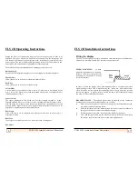
FLUSH MOUNTING
- to flush
mount the instrument cut a rectangu-
lar hole: 206 mm x 119 mm Set the
instrument on a bed of RTV silicone
(or similar sealant).
In order to secure the display when flush mounting there is a stainless steel flush
mount stirrup provided. This is attached using the plastic m6 studs and nuts pro-
vided. Please do not over tighten these mounting nuts as it may distort the case and
cause water ingress. It may be easier to thread the power cable through the stirrup
and plug it in before mounting the stirrup.
BRACKET MOUNT -
The optional bracket may be mounted on any convenient
horizontal or vertical surface using suitable screws or bolts.
·
When the correct angle of view has been chosen, Put the 25mm diameter rub-
ber washers onto the mounting Knobs.
·
Slide the threaded stud of the knobs through the two holes near the radiuses at
the edge of the bracket. (From the outside pointing in ).
·
Put the square nuts provided. loosely onto the threads of the knobs.
·
Now slide the square nuts into the bracket locator on the back of the display,
this may be easier to start one side at a time. And tighten knobs.


