background image

Echoflex Installation Guide

Magnetic Contact Sensor

Magnetic Contact Sensor (MC-31)

 Page 2 of 12

Echoflex

Installation

The MC-31 sensor has two parts: the contact sensor and the magnet. The 
sensor should be installed on the casing and the magnet on the moving 
window or door. The location of the MC-31 directly affects the quality of 
the controller’s message reception.

If installing on a beveled window or door trim, ensure the magnet is 
oriented to accommodate the angle. See 

Magnet Position Test

 on 

page 6


to confirm the location.

Use hand tools for the installation. Over-torquing with a screw gun can 
damage the device.

Mount the Sensor 

The sensor can be mounted using 
screws through the mounting plate, 
with double-sided tape, or with Velcro.

To mount with screws:

1. Insert a flatblade screwdriver into 

one of the two slots at the side 
and gently pry to remove the 
sensor from the mounting plate.

2. Mount the mounting plate using 

two #6 screws. 

3. Snap the sensor back into place.

Mount the Magnet

Orienting the magnet in relation to the 
sensor is critical. Mount the magnet 
using screws through the mounting 
plate, with double-sided tape, or with Velcro.

To mount with screws:

1. Insert a flatblade screwdriver into the single slot at the side and gently 

pry to remove the magnet from the mounting plate.

2. Mount the mounting plate using two #6 screws. To confirm the 

location relative to the sensor, see 

Magnet Position Test

 on 

page 6

.

3. Perform a thorough check to ensure normal use of the window or door 

does not damage the device. 

4. Snap the magnet back in place.

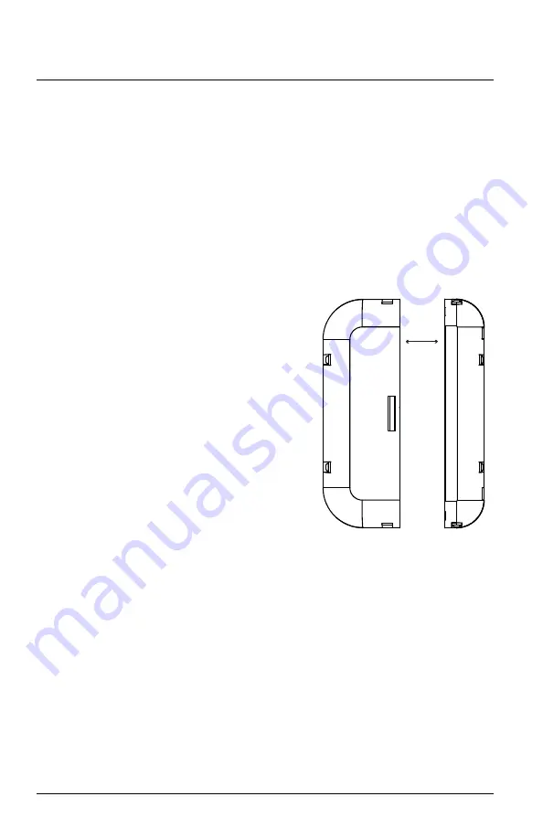
The gap between the sensor and magnet should not exceed 12.7 mm 
(1/2 in) to prevent damage when opening and closing the door. The ideal 
planar alignment of the magnet is level with the sensor. 

Magnet

Sensor

Ideal alignment (contact closed)

12.7 mm

(1/2 in)

Summary of Contents for MC-31

Page 1: ...ity applications that require control to power a room or setback temperature control devices The MC 31incorporates features that assist the installer to position the device without the need for signal...

Page 2: ...ne of the two slots at the side and gently pry to remove the sensor from the mounting plate 2 Mount the mounting plate using two 6 screws 3 Snap the sensor back into place Mount the Magnet Orienting t...

Page 3: ...refer to the related product documentation 2 Press the Teach button on the sensor once to send a message The blue LED blinks to confirm a successful transmission 3 Deactivate Link mode on the controll...

Page 4: ...he Teach button and color LEDs are used to navigate the Tests and Settings Menu The intervals between blinks make it easy to distinguish between single double and triple blinks Exit and Start Over gre...

Page 5: ...Teach button until the white LED blinks twice 2 Press and release the Teach button to cycle through the menu of color LEDs and stop when the blue LED blinks once 3 Press and hold the Teach button unti...

Page 6: ...operation a green LED blinks to indicate a contact open event and a red LED blinks to indicate a contact close event The LED Display setting controls whether the operating mode LEDs are enabled or dis...

Page 7: ...ice 2 Press and release the Teach button to cycle through the menu of color LEDs and stop when the blue LED double blinks 3 Press and hold the Teach button until the white LED blinks twice to select E...

Page 8: ...LED blink code displays the current setting Press and release the Teach button to navigate the options 4 Press and hold the Teach button until the white LED blinks twice when the target indication di...

Page 9: ...the green LED triple blinks 3 Press and hold the Teach button until the white LED blinks twice to select Heartbeat Messaging The green LED blink code displays the current setting Press and release the...

Page 10: ...le through the menu of color LEDs and stop when the blue LED triple blinks 3 Press and hold the Teach button until the white LED blinks twice to select Energy Status Messaging The blue LED blink code...

Page 11: ...3 Press and hold the Teach button until the white LED blinks twice to select Redundant Messaging The red LED blink code displays the current setting Press and release the Teach button to navigate the...

Page 12: ...anual may cause harmful interference to radio communications Any modifications or changes to this product not expressly approved by Electronic Theatre Controls Inc could void the user s authority to o...

Reviews: