background image

PN 18280-00   R041306

26

SERVICE & MAINTENANCE

BEFORE INSPECTING OR SERvICING ANY PART OF ThIS MAChINE, ShuT OFF POWER SOuRCE,  

DISENGAGE ThE hYDRAuLICS, OPEN ShIELD AND MAkE SuRE ALL MOvING PARTS hAvE COME TO A COMPLETE STOP.

WARNINg

5.7.2  REpLAcINg hYDRAuLIc DRIvE bELT

Check the condition of the drive belt annually or after every 

25 hours of operation, whichever comes first.  If the belt is 

cracked, frayed, worn or stretched, replace it. Follow proce-

dure below to replace the drive belt.
using a wrench, pull the small idler pulley away from the 

hydraulic belt to release the tension
Remove the hydraulic drive belt from the drive pulley on the 

engine and the hydraulic pump
using a wrench, pull the small idler pulley towards the center 

of the chipper
Install the hydraulic drive belt on the hydraulic pump, on out-

side of idler pulley and on engine drive pulley.(figure 5.6)
Release  idler  to  apply  tension  on  hydraulic  pump  drive 

belt.

1.

2.

3.

4.

5.

6.

5.7.2  ADjusTINg DRIvE bELTs

Lower the engagement handle
Loosen bolt on engine tie.  DO NOT REMOvE.
verify the belt tensioning bolts on the engine mount plate are 

tight against the engine mount.
Loosen the four engine mount bolts.
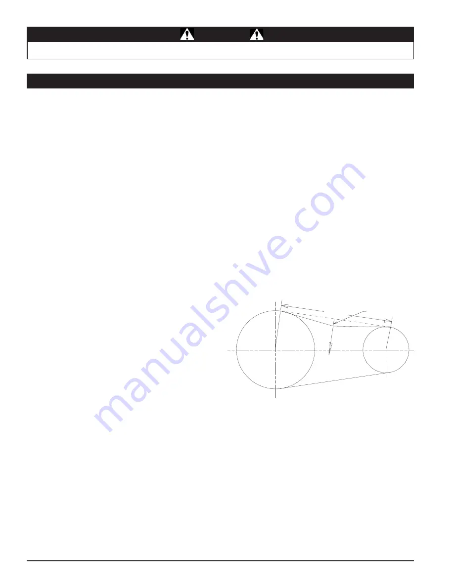
Alternately turn each of the belt tension bolts clockwise an 

equal number of turns until the belt deflection at the center 

of the belt is 7/16” when a 20 lb load is placed against the 

belt (figure 5.5)
Check pulley alignment using a straight edge and adjust the 

appropriate belt tension bolt if required.
Tighten  the  four  engine  mount  bolts  to  the  appropriate 

torque
Tighten the engine tie bolt
Lift the engagement handle, start engine and lower engage-

ment handle to test units. Adjust pulleys and belt tension as 

needed.

1.
2.
3.

4.
5.

6.

7.

8.
9.

Figure 5.5 - Drive Belt Tension

Span Length

Force
20 lbs

7/16" Deflection

5.7   DRIvE bELTs (coN'T)

Summary of Contents for Bear Cat 76824

Page 1: ...6824 24 hp TURNTABLE 76835 35 hp TURNTABLE 76824s 24 hp TURNTABLE 76835s 35 hp TURNTABLE 76835f 35 hp TURNTABLE PN 18280 00 R041306 Companion to 18281 00 MADE WITH PRIDE IN THE fR manuel du propiÉtaire en Owner s manual es manual del propietario ...

Page 2: ... bear cat address Phone e mail hours 237 NW 12th Street P O Box 849 West Fargo ND 58078 800 247 7335 701 282 5520 Fax 701 282 9522 opesales crary com service crary com Monday Friday 8 am to 5 pm Central Time SERIAL NUMBER MANUFACTURED BY CRARY INDUSTRIES MANUFACTURED IN U S A XXXXXX WEST FARGO NORTH DAKOTA 58078 U S A SERIAL NUMBER 2006 Crary industries all rights reserved produced and printed in ...

Page 3: ... including but not limited to bearings belts pulleys filters and chipper knives This warranty does not cover normal maintenance service or adjustments This warranty does not cover depreciation or damage due to misuse negligence accident or improper maintenance This warranty does not cover damage due to improper setup installation or adjustment This warranty does not cover damage due to unauthorize...

Page 4: ...FETY CHAINS 15 3 13 rear stabilizer 15 Operation 16 4 1 STARTING THE MACHINE 16 4 2 STOPPING THE MACHINE 16 4 3 rotate chipper base 16 4 4 directing the discharge tube 17 4 5 raise lower the access cover 17 4 6 feed roller speed control 17 4 7 chipper feed controller 18 4 8 feed roller control bar 18 4 9 towing 19 4 10 chipping guide 20 Service Maintenance 21 5 1 maintenance schedule 21 5 2 disk l...

Page 5: ... rester must be attached to the engine exhaust system in such a manner that flames or heat from the system will not ignite flammable material Failure of the owner operator of the equipment to comply with this regulation is a misdemeanor under California law and may also be a violation of other state and or federal regulations laws ordinances or codes Contact your local fire marshal or forest servi...

Page 6: ...s of operation Do not transport or move machine while the machine is operating or running 9 10 11 12 13 14 15 16 17 Read and understand this Owner Operator s manual Be completely familiar with the controls and the proper use of this equipment Familiarize yourself with all of the safety and operating decals on this equipment and on any of its attachments or accessories Keep safety decals clean and ...

Page 7: ...hine to come to a complete stop before clearing obstructions Set up your work site so you are not endangering traffic and the public Take great care to provide adequate warnings Do not climb on machine when operating Keep proper balance and footing at all times Check cutting chamber to verify it is empty before starting the machine The disk will continue to rotate when clutch is disengaged Shut of...

Page 8: ...all Do not exceed maximum towing speed indicated on tire sidewall Inflate tires to manufacturers specifications as stated on the tire sidewall 1 2 3 4 1 7 towing safety Optimum towing performance can be achieved by maintain ing a horizontal trailer hitch Check wheel lug bolts periodically to ensure they are tight and secure Make sure the jack stand and the rear stabilizer on trailer are in the UP ...

Page 9: ...OF INLET AND DISCHARGE OPENINGS WHILE MACHINE IS OPERAT ING TO AVOID SERIOUS PERSONAL INJURY STOP AND ALLOW MACHINE TO COME TO A COMPLETE STOP BEFORE CLEARING OBSTRUCTIONS 2 READ AND UNDERSTAND THIS OWN ER OPERATORS MANUAL BE COM PLETELY FAMILIAR WITH THE CON TROLS AND THE PROPER USE OF THIS EQUIPMENT OBTAIN AND WEAR SAFETY GLASS ES AND USE HEARING PROTECTION AT ALL TIMES WHEN OPERATING THIS MACHI...

Page 10: ...ngine manufacturer for engine safety instructions and decals Make certain that all safety and operational decals on this machine are kept clean and in good condition The decals are shown below at reduced sizes Refer to the parts catalog if you need a replacement decal Decals that need replacement must be applied to their original locations 1 9 safety decals Con t PN 18555 00 11 PN 14049 00 9 18555...

Page 11: ...manufacturer for engine safety instruc tions and decals Make certain that all safety and operating decals on this machine are kept clean and in good condition The decals are shown below at reduced sizes Refer to the parts catalog if you need a replacement decal Decals that need replacement must be applied to their original locations 1 10 SAFETY DECAL LOCATIONS 3 2 1 6 10 5 8 4 7 9 3 2 1 6 10 11 8 ...

Page 12: ...he wire harness through the hitch tube and slide the hitch tube into the trailer frame Secure using two 1 2 x 4 1 2 bolts washers and nuts provided in owner s kit Slide the hitch coupler onto the hitch tube from the top and secure using 1 2 bolts nuts and washers Thread the wire harness through the metal loop on the un derside of the coupler 1 2 3 2 3 rear stabilizer Verify that the rear stabilize...

Page 13: ...tting at the pump on this inlet line until oil bleeds out Start the engine and run at the lowest possible RPM As you purge air from the unit the oil level in the reservoir will drop and bubbles may appear in the fluid Refill the reservoir as necessary Run the feed roller in both directions for several minutes until any remaining air purges from the unit Refill the reservoir as necessary Shut down ...

Page 14: ... 3 4 Figure 2 2 Chute Extension Tray Assembly Hairpin Clip Feed Control Lever C h i p p e r Chute E x t e n s i o n Hinge E x t e n s i o n Tray Position this lip behind the lip on the chipper chute shown below Hold the extension tray directly above the chipper chute and slide it downward 2 8 chipper chute Mount the chipper chute to the chipper housing using eight 3 8 x 1 bolts and locknuts Use th...

Page 15: ...tch box cover Verify that the sensors are within 2mm 5 64 from the switch box plate and adjust if needed 1 1 2 1 2 2 11 switch box 2 10 DISCHARGE TUBE Attach the discharge tube to the mounting flange on the chip per frame Half of the mounting clamp is already attached to the tube Slide the tube onto the flange and tighten the bolts to secure it Install the second half of the clamp to the tube and ...

Page 16: ... OWNERS MANUAL FOR FURTHER ENGINE OPERATING INSTRUCTIONS 3 TURNTABLE BRAKE HITCH JACK S F MODELS CHUTE EXTENSIONTRAY S F MODELS FEED ROLLER CONTROL BAR ENGINETHROTTLE COUPLER 51 mm S F MODELS HITCH DOMESTIC MODELS COUPLER 2 HITCH JACK SAFETY CHAINS FEED ROLLER SPEED CONTROL PARK BRAKE S F MODELS SAFETY BAR TRANSPORT SAFETY PIN DISCHARGETUBE DISCHARGE CAP ENGAGEMENT HANDLE FEED ROLLER LIFT JACK REA...

Page 17: ... disk first idle the engine down and then pull the engagement handle up Controls the speed of the feed roller Allows the operator to have better control over the material being fed into the chip per Turning the knob clockwise will decrease the speed of the feed roller Turning the knob counterclockwise will increase the speed of the feed roller Locks the turntable to the frame for any chipping posi...

Page 18: ...ard to disengage drive belts Start the engine see engine owners manual 1 2 3 4 5 Move throttle to SLOW position Move engagement handle upward to disengage drive belt Shut off engine see engine owners manual Allow machine to come to a complete stop 1 2 3 4 4 1 STARTING THE MACHINE Once engine is running and no choke is needed set engine to 1 4 throttle and slowly release the engagement handle This ...

Page 19: ...djust to desired position Turn knob clockwise to secure discharge cap 4 4 directing the discharge tube 4 5 raise lower the access cover Rotate the discharge chute so it is parallel to the access cover Remove the two 3 8 x 1 1 4 bolts nuts and washers securing the access cover to the chipper housing After lowering the access cover secure the access cover to the chipper housing using two 3 8 x 1 14 ...

Page 20: ...ller Stop Switch Forward feed stopped Domestic Models Disk RPM too low S F Models Disk RPM too Low or Safety Bar Activated Safety Bar S F models only If safety bar has been activated the red LED will light up Push the reset override button to resume forward feed Figure 4 3 To overcome false trips of the safety bar by material being chipped the reset override button may be held in for 5 seconds To ...

Page 21: ...osition Raise rear stabilizer Open the coupler latch Raise the trailer hitch until the coupler is above the height of the hitch ball 2 hitch ball on the towing vehicle Align the coupler over the hitch ball and lower the trailer hitch until the coupler fully engages the hitch ball Close the coupler latch securing the coupler to the hitch ball Install the hitch pin through the coupler latch Cross th...

Page 22: ...k or brush paddle 1 2 3 4 5 6 Never use shovels or forks to feed brush They can be chipped are expensive to replace and cause extensive damage In addition metal pieces can be ejected from the chipper chute and cause serious injury or death Never feed brush into the chipper chute with your feet Place limb butt end first into the chipper chute until it con tacts the chipper blades The actual feed ra...

Page 23: ...Y CONNECTIONS CHECK NUTS BOLTS CHECK CHIPPER BLADES CHECK SHARPEN IF NEEDED 3 BELT PULLEY ALIGNMENT CHECK DRIVE BELT CHECK HYDRAULIC DRIVE BELT CHECK TIRE PRESSURE CHECK ENTIRE MACHINE CLEAN ENGINE OIL CHANGE 1 4 5 DISCHARGE TUBE GREASE DISK BEARING GREASE COOLING SHROUDS CLEAN 1 PRE CLEANER ELEMENT CLEAN 1 AIR INTAKE CLEAN 1 HYDRAULIC OIL FILTER REPLACE 4 AIR CLEANER CHECK CLEAN 1 OIL FILTER CART...

Page 24: ...g slot 1 2 3 1 2 5 3 1 Removing The Blades Remove the two 3 8 inch retaining bolts securing the access cover to the main frame assembly Tilt access cover over to allow access to disk Rotate the disk so that the bolts holding the chipper blades are accessible Install the disk lock Section 5 2 The disk is now restrained for removing the blades To access the remaining blades remove the punch or screw...

Page 25: ...1 2 3 4 5 6 7 8 9 Figure 5 3 Chipper Blade Surfaces MOUNTING SURFACE DO NOT GRIND MOUNTING SURFACE DO NOT GRIND SHARPENED SURFACE SHARPENED SURFACE 45 38 5 3 4 setting chipper Blade clearAnce The chipping blades should clear the chipper block located di rectly under the chipper chute by 1 16 to 1 8 inch Figure 5 4 To adjust the blade clearance proceed as follows Remove the two 3 8 bolts securing t...

Page 26: ...re tight and secure 3 4 5 5 plugged disk If the machine becomes plugged lift the engagement handle shut off the engine disconnect the spark plug wire and al low the machine to come to a complete stop before clearing debris Do not operate the machine without proper guards and shields in place WARNING Feeding too large or too much material at once may plug the chipper To clear a plugged disk proceed...

Page 27: ...e pulley on the engine Remove the old disk drive belt and install new disk drive belt on engine and large pulley Install large idler pulley Lower engagement handle to engage drive belt Alternately turn each of the belt tension bolts clockwise an equal number of turns until the belt deflection at the center of the belt is 7 16 when a 20 lb load is placed against the belt Figure 5 5 Check pulley ali...

Page 28: ...ump on out side of idler pulley and on engine drive pulley figure 5 6 Release idler to apply tension on hydraulic pump drive belt 1 2 3 4 5 6 5 7 2 Adjusting Drive Belts Lower the engagement handle Loosen bolt on engine tie DO NOT REMOVE Verify the belt tensioning bolts on the engine mount plate are tight against the engine mount Loosen the four engine mount bolts Alternately turn each of the belt...

Page 29: ... facing away from engine towards hinge side of rotor cover Install the four bearing mounting bolts with washers through the bearing bearing mount bracket and frame Torque to 75 ft lb 1 2 3 4 5 6 7 8 Install the bearing lock Verify that there is no shaft end play If there is no shaft end play proceed to Step 14 If end play is detected Loosen bearing spacer on belt side bearing Loosen both belt side...

Page 30: ...r bearing mounting bolts with washers through the proximity sensor bracket bearing bearing mount bracket and frame Torque to 75 ft lb Tighten the two bearing set screws Install the bearing spacer tight against the bearing and lock in place Adjust the proximity sensor to within 1 32 to 1 16 from bearing spacer bolt head Place pulley bushing on shaft Place pulley on bushing Align pulley with engine ...

Page 31: ...luids 5 9 hydraulics 5 9 2 hydraulic feed maintenance The hydraulic pump normally does not require regular fluid changes The system filter should be changed after 250 hours of operation or annual intervals The fluid and filter should be changed and system cleaned if the fluid becomes contaminated with foreign matter water dirt grease etc or if the fluid has been subjected to temperature levels gre...

Page 32: ...pplications greasing equipment and operat ing conditions In most cases it is best to lubricate in small amounts under low pressure until a thin bead of fresh grease is visible at the seal lip area 5 10 greasing Care should be taken when greasing bearings to avoid overfill ing Overfilling can lead to excessive heat and or unseating of the seals Grease should be introduced in small amounts and under...

Page 33: ...TENANCE Before inspecting or servicing any part of this machine shut off power source disengage the hydraulics open shield and make sure all moving parts have come to a complete stop WARNING Figure 5 8 Greasing Locations 50 h 200 h 100 h ...

Page 34: ... wraps around disk shaft Stringy green material bypasses chipper blades Dull chipper blades Improper blade clearance 1 2 3 Rotate branch or material when feeding to cut completely Sharpen blades Adjust clearance between the chipper blades and anvil 1 2 3 Excessive vibration while running Drive system vibration Disk out of balance Chipper blade anvil clearance is incorrect 1 2 3 Check drive belts a...

Page 35: ...100 feet min average 0 47 meters min 30 meters min average hydraulic oil tank capacity 3 gal 11 5 liters 7 1 size specifications 76835 35 HP description ENGLISH METRIC Overall size 93 x 80 x 90 241 3cm x 203 2cm x 228 6cm OVERALL weight 2 290 lbs 1039kg max chipper capacity 8 dia 20cm dia feed chute opening 30 1 4 x 30 3 4 76 8cm x 78 1cm feed table 38 long 96 5cm long chipper blades 4 reversible ...

Page 36: ...n 100 feet min average 0 47 meters min 30 meters min average hydraulic oil tank capacity 3 gal 11 5 liters does not apply to f models 76835s 35 HP s f modelS dESCRIPTION ENGLISH METRIC Overall size 93 x 80 x 90 241 3cm x 203 2cm x 228 6cm OVERALL weight 2 350 lbs 1066kg max chipper capacity 8 dia 20cm dia feed chute opening 30 1 4 x 30 3 4 76 8cm x 78 1cm feed table 38 long 96 5cm long chipper bla...

Page 37: ... SAE 5 SAE 8 N m Ft lb N m Ft lb N m Ft lb 1 4 7 5 5 5 11 8 16 12 5 16 15 11 23 17 34 25 3 8 27 20 41 30 61 45 7 16 41 30 68 50 95 70 1 2 68 50 102 75 149 110 9 16 97 70 149 110 203 150 5 8 122 90 203 150 312 230 3 4 217 160 353 260 515 380 7 8 230 170 542 400 814 600 1 298 220 786 580 1220 900 1 1 8 407 300 1085 800 1736 1280 1 1 4 570 420 2631 1940 2468 1820 A SAE 2 SAE 5 SAE 8 BOLT DIAMETER A M...

Page 38: ...NS 7 3 hydraulic schematic HYDRAULIC RESERVIOR 16588 FILTER ASSEMBLY 16922 REPLACEMENT FILTER HYD OIL FILTER 18525 00 2 STAGE PUMP 2500 PSI 1 GPM 18527 00 VALVE ASSEMBLY PRESSURE SWITCH 2300 PSI 16586 FEED ROLLER MOTOR A B P T MR 80 PSI ...

Page 39: ...LACK WHITE RED YELLOW RED LT GREEN RED RED BLACK RED ORANGE WHITE RED GREEN WHITE BROWN BLACK BLUE BROWN BLACK BLUE RED RED BLACK RED LT GREEN RED BLACK BROWN BLACK BLUE DISK SENSOR PRESSURE SWITCH SAFETY BAR SWITCH RESET OVERRIDE SWITCH REVERSE SENSOR FORWARD SENSOR 14864 00 N C MOMENTARY PLUNGER 14865 00 N O MOMENTARY PUSHBUTTON 18472 00 PROXIMITY SENSOR REPLACEMENT ONLY EUROPEAN S F MODELS ONLY...

Reviews: