background image


11 

Installation of Completed Crossover Assemblies 

1.


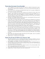
Inside  the  speaker  cabinet,  strip  the  ends  of  the  L

-

pad  and  driver  wires  that  were 

previously snipped away from the factory PCB, twist the strands together, and tin the 
ends of the wires with solder. 

2.


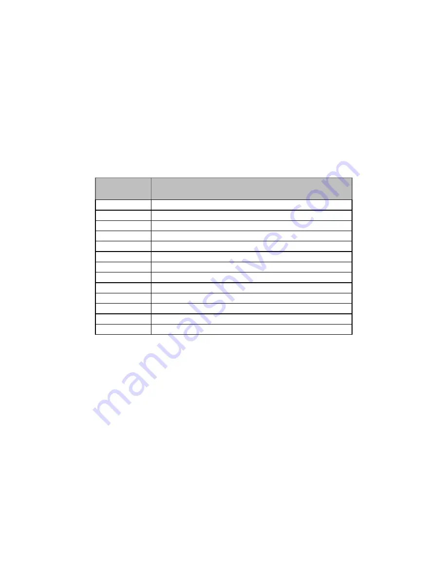
Solder the wires inside the cabinet to their proper PCB pads according to the table below.  
The  wire  color  codes  shown  in  the  table  are  consistent  both  with  the  4425  speakers 
we’ve tested and the original 4425 technical manual from JBL.  Route the wires along the 
bottom side of the board, bring them up and around the bottom edge of the PCB, and 
Insert the wires into the PCB pads from the top side of the board – this will offer strain 
relief of these connections (again, use Figure 3 as an example of how it should look).  
Double check the wiring against the table below, and then solder the wires to the PCB. 


3.


Thread a zip tie through the zip tie mount you adhered to the assembly in the previous 
section, so that it’s facing up.  Bundle the wires from the bottom side of the PCB together 
and use the zip tie to secure the bundle.  Before tightening it fully, make sure there is no 
excessive  strain  on  the  connections  to  the  PCB,  nor  excess  slack  in  the  wire  routing 
underneath the PCB.  You can push/pull the wires through your semi

-

tightened zip tie 

loop until you have everything dressed properly, and then tighten it fully and snip off the 
excess length. 

4.


Align the assembly mounting holes with their mounting points on the back wall of the 
speaker and use the six original Philips head screws to securely mount the assembly to 
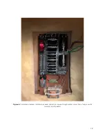
the cabinet.  An example of a finished, mounted assembly is shown in Figure 4. 

5.


Connect the green wire from the crossover to the red (+) terminal on the woofer and 
connect the green/black striped wire to the black (

-

) terminal on the woofer. 

6.


Lower the woofer in to the cabinet, align the holes on the woofer with the holes on the 
baffle, and use the original mounting screws to secure it. 

7.


Repeat steps 1 through 6 for the other crossover assembly and speaker cabinet. 

8.


You’re all done!  Fire up some tunes and enjoy the upgraded sonic experience! 
 

PCB Pad 

Designator

Connection

E1

Red wire to speaker input +

E2

Black wire to speaker input 

-

E3

Enameled wire from stock inductor

E4

Enameled wire from stock inductor

E5

Green wire to LF driver red terminal

E6

Green/black wire to LF driver black terminal

E7

Yellow wire to HF driver red terminal

E8

Yellow/black wire to HF driver black terminal

E9

Green wire to L

-

Pad R202 pin 3

E10

Orange wire to L

-

Pad R202 pin 1

E11

Black wire to L

-

Pad R202 pin 2

E12

White wire to L

-

Pad R201 pin 2

E13

Red wire to L

-

Pad R201 pin 1


Summary of Contents for JBL 4425

Page 1: ...JBL Model 4425 Charge Coupled Crossover User Manual echomountainaudio com echo mountain audio altadena california...

Page 2: ...E 14 Introduction Thank you for your purchase of Echo Mountain Audio s charge coupled crossover boards for the JBL Model 4425 Studio Monitor The set of bare boards you have received are intended for D...

Page 3: ...specs home speakers 1993 k2 s5500 page10 jpg http www lansingheritage org images jbl specs home speakers 1993 k2 s5500 page11 jpg http www lansingheritage org images jbl specs home speakers 1993 k2 s5...

Page 4: ...sting snap lock PCB clips An example of a completed crossover installed in the factory crossover housing is shown in Figure 3 Note that the default configuration uses the factory inductor for the woof...

Page 5: ...5 Figure 2 PCB bottom side view...

Page 6: ...pendix A and on Solen s product page Components of the same type and rating from other manufacturers may be substituted at the user s discretion but it is the responsibility of the user to measure the...

Page 7: ...s close to the PCB as possible they should all be accessible from the top side of the board 6 Once the wires are de soldered or cut from the PCB you will need to remove them from the strain relief cla...

Page 8: ...sidue with a swab and isopropyl alcohol 2 Insert and solder the small 0 25W resistors RC1 RC3 RC5 RC8 on the top side of the board Clean off any residual flux residue with a swab and isopropyl alcohol...

Page 9: ...rint so trim off the excess length leaving enough to pass through the board and allow for a solder fillet on both sides 3 Now that you ve trimmed off the excess leads to the desired length you ll need...

Page 10: ...enter it and then remove the protective layer on the exposed side of double sided tape Place the battery and clip down on the right side of the crossover assembly mounting plate choosing the location...

Page 11: ...neath the PCB You can push pull the wires through your semi tightened zip tie loop until you have everything dressed properly and then tighten it fully and snip off the excess length 4 Align the assem...

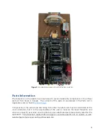
Page 12: ...12 Figure 4 Completed crossover installed in speaker cabinet as viewed through woofer cutout top of image points towards top of speaker...

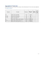
Page 13: ...6 2 uF PA Series 250V Solen PA620 2 4 C5A C5B Capacitor 8 2 uF PA Series 250V Solen PA820 2 4 C8A C8B Capacitor 16 uF PA Series 250V Solen PA1600 2 4 L1 Inductor 1 0 mH Air Core Solen S201 0 1 2 R1 R...

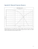
Page 14: ...Mountain Charge Coupled Crossover blue curves was obtained using 8 ohm dummy loads with an RME ADI 2 Pro FS R BE audio interface and REW software 40 35 30 25 20 15 10 5 0 20 200 2000 20000 Magnitude...

Reviews: