background image

Chengdu Ebyte Electronic Technology Co.,Ltd

ME31-AXXX8000_UserManual_CN

Copyright ©2012–2023

Chengdu Ebyte Electronic Technology Co.,Ltd

9

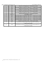
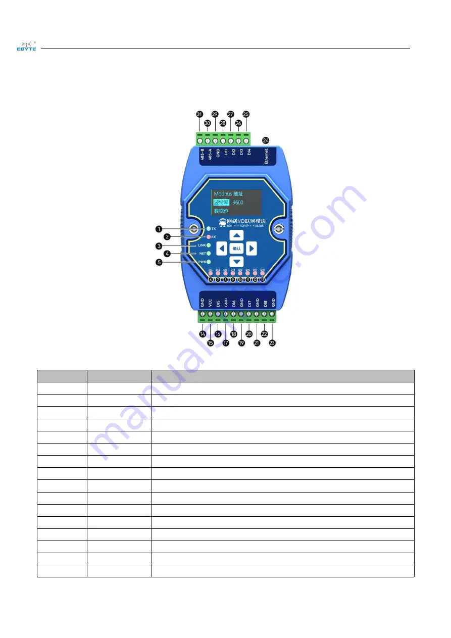
3.4 Ports and indicators

No.

Sticker

Remarks

1

TX

LED

UART TX data

2

RX

LED

UART RX data

3

LINK

LED

Network link

4

NET

LED

Network data TX and RX

5

PWR

LED

Power input

6

DI1

LED

Switch input indicator of channel 1

7

DI2

LED

Switch input indicator of channel 2

8

DI3

LED

Switch input indicator of channel 3

9

DI4

LED

Switch input indicator of channel 4

10

DI5

LED

Switch input indicator of channel 5

11

DI6

LED

Switch input indicator of channel 6

12

DI7

LED

Switch input indicator of channel 7

13

DI8

LED

Switch input indicator of channel 8

14

GND

Negative pole of power input terminal

DC 8V~28V

5.08mm phoenix terminal

15

VCC

Positive pole of power input terminal

DC 8V~28V

5.08mm phoenix terminal

16

DI5

Switch input channel 5, support dry contact access

5.08mm phoenix terminal

Summary of Contents for ME31-AXXX8000

Page 1: ...ME31 AXXX8000 I O Networking Module...

Page 2: ...introduction 11 4 1DI input 11 4 1 1Switch input DI acquisition 11 4 1 2 Input filtering 11 4 2 Modbus gateway 11 4 2 1 Modbus TCP RTU Protocol Conversion 11 4 2 2 Modbus address filtering 11 4 2 3 M...

Page 3: ...Technology Co Ltd ME31 AXXX8000_UserManual_CN Copyright 2012 2023 Chengdu Ebyte Electronic Technology Co Ltd II 5 Host computer 21 5 1 Acquisition and control 21 5 2 Parameter Configuration Interface...

Page 4: ...n local Modbus addresses through the serial port network port 1 2 Features Good for standard Modbus RTU protocol and MODBUS TCP protocol Work with various configuration software PLC touch screen RS485...

Page 5: ...tronic Technology Co Ltd ME31 AXXX8000_UserManual_CN Copyright 2012 2023 Chengdu Ebyte Electronic Technology Co Ltd 2 1 3 Application typology diagram Network port application topology Serial port app...

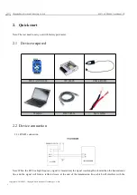
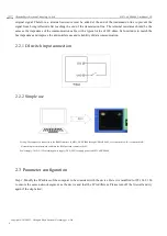
Page 6: ...ith factory parameter 2 1 Devices required ME31 AXXX8000 12V SMPS USB to RS485 Computer RJ45 Cable More cables 2 2 Device connection 2 2 1 RS485 connection Note When the 485 bus high frequency signal...

Page 7: ...ove the anti interference and reliability of data communication 2 2 1 DI switch input connection 2 2 2 Simple use Wiring The computer is connected to the RS485 interface of ME31 AXXX8000 through USB t...

Page 8: ...c Technology Co Ltd 5 Step 2 Open the network assistant select the TCP client enter the remote host IP192 168 3 7 default parameters enter the port number 502 default parameters and select HEX to send...

Page 9: ...r function according to below table Function function code Command Read all DI state 0x02 01 00 00 00 00 06 01 02 00 00 00 08 2 4 2 Modbus RTU Control Use network assistant to control ME31 AXXX8000 fi...

Page 10: ...RTU MODBUS Device address Modify via Modbus command and computer DI input DI channels 8 channel Input type Default dry node Acquisition frequency 1 kHz Input indicator OLED display red LED Others Pro...

Page 11: ...ic Technology Co Ltd 8 DHCP Off Local MAC Depending on chip fixed Target IP 192 168 3 3 Target port 502 DNS server 114 114 114 114 Active upload Off UART parameter Baud rate 9600bps 8 type Check metho...

Page 12: ...D Switch input indicator of channel 2 8 DI3 LED Switch input indicator of channel 3 9 DI4 LED Switch input indicator of channel 4 10 DI5 LED Switch input indicator of channel 5 11 DI6 LED Switch input...

Page 13: ...cess 5 08mm phoenix terminal 23 GND Channel 8 switch input ground 5 08mm phoenix terminal 24 Ethernet Standard RJ45 interface 25 DI4 Switch input channel 4 support dry contact access 5 08mm phoenix te...
Page 14: ...efault 6 sampling periods 6 1kHz It can be configured with the host computer through instructions 4 2 Modbus gateway The device can transmit non local Modbus instructions from the network serial port...

Page 15: ...nction Code Data Segment Check code CRC 1 Bit 1 Bit N Bit 2 Bit For example get DI state command 01 02 00 00 00 04 79 C9 Device Modbus address Function Code Data Segment CRC check code 4 3 Active uplo...

Page 16: ...ble 5 Gateway address gateway 6 DHCP Set the way the device obtains IP static 0 dynamic 1 7 Target IP When the device works in client mode the target IP or domain name of the device connection 8 Targe...

Page 17: ...parameters 4 5 1 Information display interface Including the current input value display page shortly press the left and right buttons to switch the interface 4 5 2 Device parameter display interface...

Page 18: ...item represents the selected item and enters the setting item Adjust parameter values After selecting the setting option the up and down keys can change the numerical value or optional values Press t...

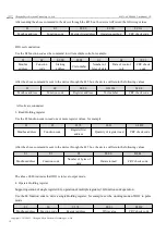
Page 19: ...range is 1 16 the smaller the number the more sensitive the larger the more stable the default is 6 R 0x03 W 0x06 0x10 DI pulse count value 0x09DF Holding register 8 RW Enter count value R 0x03 W 0x0...

Page 20: ...ally get IP R 0x03 W 0x06 0x10 Target IP Domain Name 0x08A3 Holding register 64 RW Store in strings IP Domain Name Default IP 192 168 3 3 R 0x03 W 0x06 0x10 Server port 0x08E3 Holding register 1 RW 0...

Page 21: ...coil status 01 function code to read the output coil status for example 01 01 00 00 00 04 3D C9 Modbus address Function code Register first address Output coil quantity CRC check code After the above...

Page 22: ...54 08 Modbus address Function code Register address Coil number CRC check code All coils are conducted 3 Read Holding register Use the 03 function code to read one or more register values for example...

Page 23: ...ite multiple holding register commands for example set the working mode of DO1 and DO2 at the same time 01 10 05 78 00 02 04 00 01 00 01 5A 7D Modbus address Function code Register first address Regis...

Page 24: ...to the device 1 The device can be configured by selecting interfaces serial network If you choose a network port you need to first select the network card before searching for devices 2 If you select...

Page 25: ...ter IO monitoring The following is the IO monitoring screen display 5 2 Parameter Configuration Interface Step 1 Connect the device according to Collection and Control Step 2 You can configure device...

Page 26: ...du Ebyte Electronic Technology Co Ltd 23 Step 3 After configuring the parameters click to download them In the log output you will see a prompt stating that the parameters have been successfully saved...

Page 27: ...rks Issued by 1 0 2023 06 06 First version LT About us Technical support support cdebyte com Documents and RF Setting download link http www cdebyte com Thank you for using Ebyte products Please conta...

Reviews: