background image

Chengdu Ebyte Electronic Technology Co.,Ltd.

E95-DTU(900SLxx-485) User Manual

Copyright ©2012–2022

Chengdu Ebyte Electronic Technology Co.,Ltd.

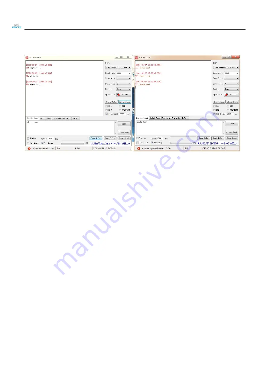
Start two serial port debugging assistants, select the serial port baud rate as 9600bps (default), and check the mode
as 8N1, then the serial port transparent transmission can be realized.

If the customer needs to switch the working mode, it can be controlled by the Mode button to switch between
different working modes (M0 indicator light, M1 indicator light). Press and hold the Mode button for about 1ms
and then release it to switch the mode once. The mode switching details are shown in the table below

Summary of Contents for E95-DTU

Page 1: ...E95 DTU 900SLxx 485 ...

Page 2: ...ers 8 3 7 Send and receive length and subcontracting method 8 4 Detailed function 9 4 1 Fixed point emission hexadecimal 9 4 2 Broadcast transmission hexadecimal 9 4 3 broadcast address 9 4 4 listen address 10 5 Operating mode 10 5 1 Transparent transmission mode mode 0 10 5 2 WOR mode mode1 11 5 3 Configuration Mode mode2 11 5 4 Deep sleep mode mode3 11 6 Register read and write control 12 6 1 In...

Page 3: ...y rights Reproduction use modification or disclosure to third parties of this document or any part thereof without the express permission of EBYTE is strictly prohibited The information contained herein is provided as is and EBYTE assumes no liability for the use of the information No warranty either express or implied is given including but not limited with respect to the accuracy correctness rel...

Page 4: ...onal LoRa digital radio With data encryption sub packet length can be set Adopt flame retardant plastic shell guide rail type installation structure convenient and efficient installation Use hidden buttons to switch the working mode to avoid false triggering and the operation of the equipment is more reliable Simple and high efficiency power supply design support power adapter or pressure line met...

Page 5: ...atchdog with precise time layout once an abnormality occurs the radio will automatically restart and can continue to work according to the previous parameter settings 1 3 Quick start You need to prepare two E95 DTU 900SLxx 485 First install the antenna for the digital radio and then install the power supply The user can choose the power adapter to supply power according to their needs Use USB to R...

Page 6: ... 9600bps default and check the mode as 8N1 then the serial port transparent transmission can be realized If the customer needs to switch the working mode it can be controlled by the Mode button to switch between different working modes M0 indicator light M1 indicator light Press and hold the Mode button for about 1ms and then release it to switch the mode once The mode switching details are shown ...

Page 7: ...g state of the radio and the user can configure the radio through the host computer configuration software Mode 3 sleep mode On On radio goes to sleep Note The radio has the function of power down saving mode the factory default setting is transparent transmission mode the user needs to switch the corresponding mode according to the M1 and M0 indicators effective immediately 1 4 Description of eac...

Page 8: ...r Blinks when sending data 7 RXD Receive indicator Blinks when receiving data 8 MO Mode indicator Working mode indicator 9 M1 Mode indicator Working mode indicator 1 5 Installation size 2 Interface definition 2 1 Power interface description E95 DTU 900SLxx 485 can be powered by 8 28V DC power supply and the wiring port is connected by wiring terminal 2 Pin ...

Page 9: ...nterface 4 TX RS232 bus TX interface The RS232 interface TX interface is connected to the device RX interface 5 RX RS232 bus RX interface The RS232 interface RX interface is connected to the device TX interface Note When the radio is connected with multiple devices the communication is not smooth but there is no such phenomenon when a single device is connected Please try to connect a 120Ω resisto...

Page 10: ...e 5g 3 Working temperature 40 85 Industrial grade 4 Voltage range 8 28V DC 12V or 24V recommended for DC version 5 Communicatio n interface RS485 RS485 6 baud rate 出厂默认 9600 Baud rate range 1200 115200 7 address code 出厂默认 0 A total of 65536 address codes can be set 3 3 Frequency range and number of channels Model Specifications Default frequency Frequency range channel spacing number of channels H...

Page 11: ...irspeed be as low as possible 3 6 Current parameters Model Specifications Emission current mA receive current mA sleep current mA 12V 12V 12V E95 DTU 900SL22 485 32 65 14 58 7 29 E95 DTU 900SL30 485 158 4 15 8 7 73 Note It is recommended to reserve more than 50 current margin when selecting the power supply which is conducive to the long term stable operation of the radio 3 7 Send and receive leng...

Page 12: ...d point emission hexadecimal 4 2 Broadcast transmission hexadecimal 4 3 broadcast address Example Set the address of radio A to 0xFFFF and the channel to 0x04 When station A is used as a transmitter same mode transparent transmission mode all receiving stations under the 0x04 channel can receive data to achieve the purpose of broadcasting ...

Page 13: ...less open transparent transmission factory default mode support special command air configuration Mode 1 WOR mode Off On Can be defined as WOR sender and WOR receiver support air wake up Mode 2 Configuration mode On Off The user accesses the register through the serial port to control the working state of the radio and the user can configure the radio through the host computer configuration softwa...

Page 14: ... transmission receive Data can be received normally and the receiving function is equivalent to mode 0 5 3 Configuration Mode mode2 Type When the M0 indicator is off the M1 indicator is on the radio works in mode 2 Transmit Can be configured wirelessly Receive Can be configured wirelessly Configuratio n User can access registers to configure radio working status 5 4 Deep sleep mode mode3 Type When...

Page 15: ...re the radio address 0x1234 network address 0x00 serial port 9600 8N1 and airspeed 1 2K at the same time Send C0 00 04 12 34 00 61 Return C1 00 04 12 34 00 61 2 read register Instruction C1 start address length Response C1 start address length parameter Example 1 Reading a channel Command Start Address Length Parameter Send C1 05 01 Return C1 05 01 09 Example 2 Read radio address network address s...

Page 16: ...yte and low byte Note When the station address is equal to FFFF it can be used as a broadcast and monitoring address that is the station will not perform address filtering at this time 01H Rea d wr ite AD DL ADDL default 0 02H Rea d wr ite NET ID NETID default 0 Network address used to distinguish the network When communicating with each other they should be set to the same 03H Rea d wr ite RE G0 ...

Page 17: ...eiving end is presented as uninterrupted continuous output If the data sent by the user is larger than the packet length the serial port of the receiving end will be output in packets 0 0 240 ebytes default 0 1 128 ebytes 1 0 64 ebytes 1 1 32 ebytes 5 RSSI Ambient Noise Enable After it is enabled the C0 C1 C2 C3 instruction can be sent in the transmission mode or the WOR transmission mode to read ...

Page 18: ...d to use in conjunction with fixed point mode that is the destination address and the source address are different 0 Disable relay function default 1 Enable relay function 4 LBT enable After enabling the wireless data will be monitored before transmission which can avoid interference to a certain extent but may cause data delay The maximum stay time of LBT is 2 seconds and it will be issued forcib...

Page 19: ... 1 1 0 3500ms 1 1 1 4000ms 07H Writ e CR YPT _H Key high byte default 0 write only read returns 0 Used for encryption to avoid interception of air wireless data by similar radio stations The radio will use these two bytes as a calculation factor to transform and encrypt the air wireless signal 08H Writ e CR YPT _L key low byte default 0 80H 86H Rea d PID PID Product Information 7 bytes PID Product...

Page 20: ...ring which the AUX output is low Relay networking rules description 1 Forwarding rules the relay can forward data between two NETIDs in both directions 2 In repeater mode ADDH ADDL is no longer used as a radio address but as a NETID forwarding pairing 如图 primary relay Node 1 NETID is 08 Node 2 NETID is 33 The ADDH ADDL of relay 1 are 08 and 33 respectively So the signal sent by node 1 08 can be fo...

Page 21: ...lue range of each parameter is as follows Network address 0 65535 Frequency channel 0 81 Network ID 0 255 Key 0 65535 Users need to pay special attention when using the host computer to configure the relay mode because in the host computer each parameter is displayed in decimal mode so the radio address and network ID need to be converted to decimal when filling in the station address and network ...

Page 22: ... mode Light on Light off The radio can only be programmed using the configuration software in the current mode 1 Programming can only be carried out in a specific working mode see the above table If the programming fails please confirm whether the working mode of the radio is correct 2 If you don t need complicated programming to open tconfiguration software you can modify the relevant parameters ...

Page 23: ...22 5 New generation LoRa rail type RS232 E90 DTU SL series interoperability DC power supply E95 DTU 400SL30 485 RS48 5 410 125 493 125 30 10 A new generation of LoRa rail type RS485 E90 DTU SL series interoperability DC power supply E95 DTU 400SL30 232 RS23 2 410 125 493 125 30 10 New generation LoRa rail type RS232 E90 DTU SL series interoperability DC power supply E95 DTU 400SL22P 48 5 RS48 5 41...

Page 24: ...perability high protection DC power supply E96 DTU 400SL22 485 RS48 5 410 125 493 125 22 5 A new generation of LoRa rail type RS485 E90 DTU SL series interoperability AC power supply E96 DTU 400SL22 232 RS23 2 410 125 493 125 22 5 A new generation of LoRa rail type RS232 E90 DTU SL series interoperability AC power supply E96 DTU 400SL30 485 RS48 5 410 125 493 125 30 10 A new generation of LoRa rai...

Page 25: ...strial automation system as shown below 13 Precautions for use 1 Do not operate the radio in the vicinity of some flammable places such as coal mines or explosive dangerous objects such as detonators for detonation A suitable DC regulated power supply should be selected which requires strong anti high frequency interference small ripple and sufficient load capacity it is best to have functions suc...

Page 26: ...on distance is often affected by temperature humidity obstacle density obstacle volume and electromagnetic environment in order to ensure stable communication it is recommended to reserve more than 50 The communication distance margin of If the measured communication distance is not ideal it is recommended to analyze and improve the communication distance based on the antenna quality and the insta...

Page 27: ...ion revision date Revision Notes Maintenance man 1 0 2022 05 18 initial version XXN 1 1 2022 06 15 Content revision XXN About us Sales Hotline 4000 330 990 Company Tel 028 61399028 Technical support support cdebyte com Official website www ebyte com Company Address Building B5 No 199 West District Avenue High tech West District Chengdu City Sichuan Province ...

Reviews: