background image

Chengdu Ebyte Electronic Technology Co., Ltd.

E34-2G4D27D User manual

Copyright ©2012–2018, Chengdu Ebyte Electronic Technology Co.,Ltd.

12

1

0

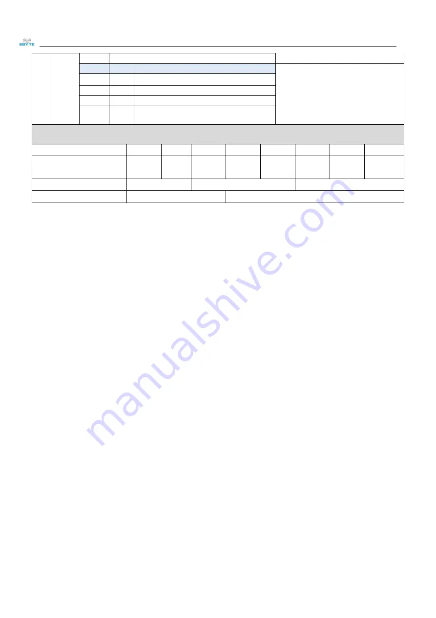
Transmitting power(Approximate value)

The external power must make sure the
ability of current output more than 200mA
and ensure the power supply ripple within
100mV;
Low power transmission is not recommended

due to its low power supply efficiency.

0

0

20dBm

default

0

1

17dBm

1

0

14dBm

1

1

10dBm

For example: The meaning of No.3 "SPED" byte

The binary bit of the byte

7

6

5

4

3

2

1

0

The specific value

(user configures)

0

0

0

1

1

0

0

0

Meaning

UART parity bit 8N1

UART baud rate is 9600

Air rate adaptation

Corresponding hexadecimal

1

8

8. Hardware Design

It is recommended to use DC stabilized power supply to supply power to the module. The power supply ripple
coefficient is as small as possible, and the module needs to be reliably grounded.

Please pay attention to the correct connection of the positive and negative poles of the power supply. If the reverse
connection is connected, the module may be permanently damaged.

Please check the power supply to ensure that between the recommended supply voltage, if exceeding the maximum,
the module will be permanently damaged.

Please check the stability of the power supply, the voltage can not be significantly frequent.

When designing the power supply circuit for the module, it is often recommended to reserve more than 30% of the
margin, and the whole machine is beneficial for long-term stable operation.

The module should be as far away as possible from the power supply, transformers, high-frequency wiring and other
parts with large electromagnetic interference.

High-frequency digital traces, high-frequency analog traces, and power traces must be avoided under the module. If
it is necessary to pass through the module, assume that the module is soldered to the Top Layer, and the copper is
spread on the Top Layer of the module contact part(All copper-covered and well grounded), and must be close to
the digital part of the module and routed in the Bottom Layer.

Assuming the module is soldered or placed in the Top Layer, it is also wrong to randomly route the Bottom Layer or
other layers, which will affect the module's spurs and receiving sensitivity to varying degrees.

Assuming that there are devices with large electromagnetic interference around the module, the performance of the
module will also be greatly affected. According to the intensity of the interference, it is suggested to stay away from
the module appropriately. If circumstances permit, appropriate isolation and shielding can be done.

Assume that there are traces with large electromagnetic interference around the module (high-frequency digital,
high-frequency analog, power trace), which will greatly affect the performance of the module. It is recommended to
stay away from the module according to the strength of the interference. If necessary, appropriate isolation and
shielding can be done;

If the communication line uses a 5V level, a 1k-5.1k resistor must be connected in series (not recommended, there is
still a risk of damage).

Try to stay away from some physical layers and also have a 2.4GHz TTL protocol, for example: USB3.0

The antenna must not be installed inside the metal case, which will greatly reduce the transmission distance.

Summary of Contents for E34-2G4D27D

Page 1: ...E34 2G4D27D User Manual nRF24L01 2 4GHz TTL Full Duplex Wireless Module...

Page 2: ...itting 6 5 2 3 Configuration procedure of module 7 5 2 4 Notes for AUX 7 6 Operating mode 7 6 1 Mode switching 8 6 2 Half Duplex Mode 0 8 6 3 Full Duplex Mode 1 8 6 4 Reservation Mode Mode 2 9 6 5 Set...

Page 3: ...uction use modification or disclosure to third parties of this document or any part thereof without the express permission of EBYTE is strictly prohibited The information contained herein is provided...

Page 4: ...he data interception loses its meaning through strict encryption and decryption algorithms The data compression function has the probability of reducing the transmission time reducing the probability...

Page 5: ...le Blocking power dBm 10 Chances of burn is slim when modules are used in short distance Operating temperature 40 85 Industrial grade 2 2 Operating parameter Main parameter Performance Remark Min Typ...

Page 6: ...emark Distance for reference 5000m Test condition clear and open area antenna gain 5dBi antenna height 2 5m baud rate 9600 FIFO 29Byte Maximum length of single transmission Buffer Size 2048 Btye Unlim...

Page 7: ...utput TTL UART outputs connects to external RXD MCU PC input pin Can be configured as open drain or push pull output 5 AUX Output To indicate module s working status wakes up the external MCU During t...

Page 8: ...er there are data that are yet to send via wireless way or whether all wireless data has been sent through UART or whether the module is still in the process of self check initialization 5 2 1 Indicat...

Page 9: ...in the new mode immediately until AUX rising edge 2ms later If AUX is on the high level the operating mode switch can be effected immediately When the user switches to other operating modes from mode...

Page 10: ...ta termination unless continuous data inputted by user Then the module will transmit all the data through wireless channel When the module receives the first data packet from user the AUX outputs low...

Page 11: ...rameters through specific instruction format pls refer to parameters setting for details Notes When the mode changes from setting mode to others the module will reset its parameters during which the A...

Page 12: ...Three C3 are sent in hexadecimal format The module returns the version information and must be send in succession 5 C4 C4 C4 Three C4 are sent in hexadecimal format The module will reset one time and...

Page 13: ...ent between communication parties 0 0 8N1 Default 0 1 8O1 1 0 8E1 1 1 8N1 equal to 00 5 4 3 TTL Serial port rate bps UART baud rate can be different between communication parties The UART baud rate ha...

Page 14: ...ower supply transformers high frequency wiring and other parts with large electromagnetic interference High frequency digital traces high frequency analog traces and power traces must be avoided under...

Page 15: ...e lower the voltage is the lower the transmitting power is Due to antenna quality or poor matching between antenna and module 9 2 Module is easy to damage Please check the power supply and ensure it i...

Page 16: ...21 36 frequency hopping anti interference 12 Antenna Type The antenna plays an important role in the communication process The inferior antenna often has a great impact on the communication system Th...

Page 17: ...ate Description Issued by v1 0 2021 9 24 Original version Linson About us Technical support support cdebyte com Documents and RF Setting download link www ebyte com Thank you for using Ebyte products...

Reviews: