background image

Chengdu Ebyte Electronic Technology Co., Ltd.

E10-433MD3 User Manual

Copyright ©2012–2018

Chengdu Ebyte Electronic Technology Co.,Ltd.

8

distance).

The power supply low voltage under room temperature is lower than 2.5V, the lower the voltage, the lower the
transmitting power.

Due to antenna quality or poor matching between antenna and module.

6.2 Module is easy to damage

Please check the power supply source, ensure it is 2.0V~3.6V, voltage higher than 3.6V will damage the module.

Please check the stability of power source, the voltage cannot fluctuate too much.

Please make sure antistatic measure are taken when installing and using, high frequency devices have electrostatic
susceptibility.

Please ensure the humidity is within limited range, some parts are sensitive to humidity.

Please avoid using modules under too high or too low temperature.

6.3 BER(Bit Error Rate) is high

There are co-channel signal interference nearby, please be away from interference sources or modify frequency and
channel to avoid interference;

Poor power supply may cause messy code. Make sure that the power supply is reliable.

The extension line and feeder quality are poor or too long, so the bit error rate is high;

7 Production guidance

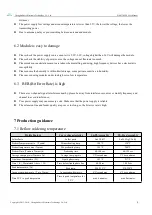
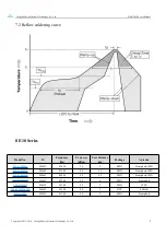
7.1 Reflow soldering temperature

Profile Feature

Curve characteristics

Sn-Pb Assembly

Pb-Free Assembly

Solder Paste

Solder paste

Sn63/Pb37

Sn96.5/Ag3/Cu0.5

Preheat Temperature min

Tsmin

Min preheating temp.

100℃

150℃

Preheat temperature max (Tsmax)

Mx preheating temp.

150℃

200℃

Preheat Time (Tsmin to Tsmax)(ts)

Preheating time

60-120 sec

60-120 sec

Average ramp-up rate(Tsmax to Tp)

Average ramp-up rate

3℃/second max

3℃/second max

Liquidous Temperature (TL)

Liquid phase temp.

183℃

217℃

Time

tL

Maintained Above

TL

Time below liquid phase line

60-90 sec

30-90 sec

Peak temperature

Tp

Peak temp.

220-235℃

230-250℃

Aveage ramp-down rate

Tp to Tsmax

Aveage ramp-down rate

6℃/second max

6℃/second max

Time 25℃ to peak temperature

Time to peak temperature for

25℃

max 6 minutes

max 8 minutes

Summary of Contents for E10-433MD3

Page 1: ...E10 433MD3 User Manual SI4438 433MHz 100mW SMD Wireless Module...

Page 2: ...parameter 4 3 Size and pin definition 5 4 Basic operation 6 4 1 Hardware design 6 4 2 Software editing 6 5 Basic application 7 5 1 Basic circuit diagram 7 6 FAQ 7 6 1 Communication range is too short...

Page 3: ...uction use modification or disclosure to third parties of this document or any part thereof without the express permission of EBYTE is strictly prohibited The information contained herein is provided...

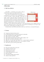
Page 4: ...it has made great progress in receiving current receiving sensitivity transmitting power receiving rate range and anti interference ability High precision 26MHz crystal is used Since the module is a...

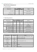
Page 5: ...be at risk of burning down Operating temperature 40 85 Industrial design Operating frequency MHz 425 433 525 Support ISM band Power consumpti on TX current mA 80 Instant power consumption RX current...

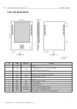
Page 6: ...en working See SI4463 manual for more details 3 NC 4 nSEL input SPI Chip select for starting SPI communication 5 MOSI input SPI master output slave input 6 GND Ground 7 MISO output SPI master input sl...

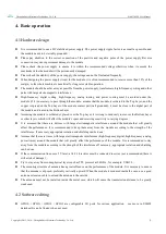
Page 7: ...suming the module is soldered or placed over the Top Layer it is wrong to randomly route over the Bottom Layer or other layers which will affect the module s spurs and receiving sensitivity to varying...

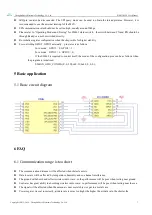
Page 8: ...GPIO3 1 In rx mode GPIO2 1 GPIO3 0 If the SI4463 is required to control itself the mode of the configuration pins can be as follows when the program is initialized SI44XX_GPIO_CONFIG 0 0 32 0x40 33 0...

Page 9: ...el signal interference nearby please be away from interference sources or modify frequency and channel to avoid interference Poor power supply may cause messy code Make sure that the power supply is r...

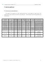
Page 10: ...o IC Frequency Hz Tx power dBm Test distance km Package Antenna E10 868MS30 SI4463 868M 30 6 SMD Stamp hole IPEX E10 915MS20 SI4463 915M 20 2 5 SMD Stamp hole IPEX E10 868MS20 SI4463 868M 20 2 5 SMD S...

Page 11: ...re TX433 NP 4310 PCB 433M SMA J 2 43 8 9 5mm Built in FPC antenna TX433 JW 5 Rubber 433M SMA J 2 50mm Flexible omnidirectional TX433 JWG 7 Rubber 433M SMA J 2 5 75mm Flexible omnidirectional TX433 JK...

Page 12: ...2017 10 16 Initial version huaa 1 10 2018 5 23 Content updated huaa 1 20 2018 9 19 Model No split Huaa About us Technical support support cdebyte com Documents and RF Setting download link www ebyte c...

Reviews: