Operating instructions
W6D500-GJ03-01
Translation of the original operating instructions
DANGER
Faulty insulation
Risk of fatal injury from electric shock
→ Use only cables that meet the specified installation
regulations for voltage, current, insulation material, capacity,
etc.
→ Route cables so that they cannot be touched by any
rotating parts.
DANGER
Electrical charge (>50 µC) between phase conductor and
protective earth connection after switching off supply
with multiple devices connected in parallel.
Electric shock, risk of injury
→ Ensure sufficient protection against accidental contact.
Before working on the electrical hookup, short the supply
and PE connections.
CAUTION
Voltage
The fan is a built-in component and has no disconnecting switch.
→ Only connect the fan to circuits that can be switched off with
an all-pole disconnection switch.
→ When working on the fan, secure the system/machine in
which the fan is installed so as to prevent it from being
switched back on.
NOTE
Water ingress into wires or cables
Water ingress at the customer end of the cable can damage the
device.
→ Make sure the end of the cable is connected in a dry
environment.
Only connect the device to circuits that can be switched off with
an all-pole disconnection switch.
4.2.1 Requirements
;
Check whether the information on the nameplate matches the
connection data.
;
Before connecting the device, make sure the power supply matches
the device voltage.
;
Only use cables designed for the current level indicated on the
nameplate.
For determining the cross-section, note the sizing criteria according
to EN 61800-5-1. The protective earth must have a cross-section
equal to or greater than that of the phase conductor.
We recommend the use of 105 °C cables. Ensure that the minimum
cable cross-section is at least
AWG 26 / 0.13 mm².
4.2.2 Residual current circuit breaker (RCCB)
If the use of a residual current device (RCD) is required in your
installation, only pulse-current sensitive and/or AC/DC-
sensitive residual current devices (type A or B) are
permissible. As with variable frequency drives, residual current
devices cannot provide personal safety while operating the
device.
4.2.3 Voltage control
NOTE
Current overshoots may occur if speed control is implemented
by transformers or electronic voltage regulators (e.g. phase
control). Depending on the type of installation of the device,
noise and vibration may also occur in the case of phase
control. Vibration can lead to bearing damage and thus
premature failure.
Heating-up of the motor when using voltage control must be checked by
the customer following installation in the end device.
4.2.4 Variable frequency drive
Please use a variable frequency drive only after consultation with ebm-
papst.
For operation with variable frequency drives, install sinusoidal
filters that work on all poles (phase-phase and phase-ground)
between the drive and the motor.
During operation with variable frequency drives, an all-pole
sine filter protects the motor against high-voltage transients that
can destroy the coil insulation system, and against harmful
bearing currents.
Heating-up of the motor when using a variable frequency drive must be
checked by the customer following installation in the end device.
4.3 Connection in terminal box
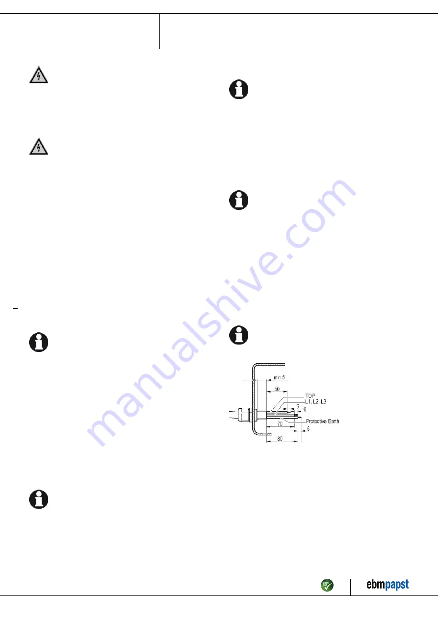
4.3.1 Preparing cables for connection
Only strip the cable as far as necessary, ensuring that the cable gland is
sealed and there is no strain on the connections. For tightening torques,
see Chapter 3.1 Product drawing.
NOTE
Tightness and strain relief are dependent on the cable
used.
→ This must be checked by the user.
4.3.2 Connecting wires to terminals
;
Remove the cap from the cable gland.
Only remove caps where cables are fed in.
;
Route the wire(s) (not included in scope of delivery) into the terminal
box.
;
First connect the "PE" (protective earth).
;
Connect the wires to the corresponding terminals.
;
Connect the thermal overload protector (TOP).
Use a screwdriver to do so.
When connecting, ensure that no wire ends fan out.
The terminal strip is equipped with a penetration guard.
;
Insert the leads until they meet resistance.
;
Seal the terminal box.
Item no. 10067-5-9970 · ENU · Change 223007 · Approved 2021-02-23 · Page 7 / 12
ebm-papst Mulfingen GmbH & Co. KG · Bachmühle 2 · D-74673 Mulfingen · Phone +49 (0) 7938 81-0 · Fax +49 (0) 7938 81-110 · [email protected] · www.ebmpapst.com


