


Operating instructions
8300100048
VBH0630CTTRS
Translation of the original operating instructions
3. TECHNICAL DATA
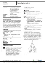
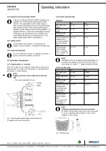
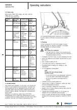
3.1 Product drawing
All dimensions in mm.
1
Installed position: shaft horizontal (install support struts only vertically as illustrated) or rotor on bottom; rotor on top on request
2
Cable diameter min. 4 mm, max. 10 mm, tightening torque 4 ± 0.6 Nm
3
Cable diameter min. 5 mm, max. 14 mm, tightening torque 6 ±0.9 Nm
(The tightening torque is designed for PVC cables. If the cable materials are different, the tightening torque may have to be adjusted)
4
Tightening torque 3 ± 0.3 Nm
5
Inlet ring with pressure tap (k-factor: 463)
6
Fastening holes for FlowGrid 00630-2-2957 (not included in scope of delivery) are provided and must be subsequently opened as required
Item no. 1170000721 · ENU · Change 262664 · Approved 2022-10-26 · Page 4 / 16
ebm-papst Mulfingen GmbH & Co. KG · Bachmühle 2 · D-74673 Mulfingen · Phone +49 (0) 7938 81-0 · Fax +49 (0) 7938 81-110 · [email protected] · www.ebmpapst.com


