


Operating instructions
8300100048
VBH0630CTTRS
Translation of the original operating instructions
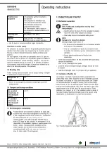
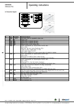
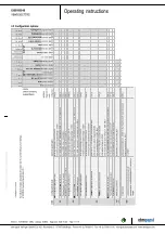
4.5 Configuration options
For further information and additional functions see EC Control Software, Fan-Set-App, or MODBUS Parameter Specification V6.3
D10
1 [.
..]
D14
7 [.
..]
D10
4 [.
..]
D12
E [.
..]
D14
8 [.
..]
D16
C [.
..]
D16
A [.
..]
(se
lec
ted
di
rec
tly
via
IO
m
ode
)
(se
lec
ted
di
rec
tly
via
IO
m
ode
)
D13
0 [0
]
D13
0 [1
]
D13
0 [2
]
D13
0 [5
]
D00
C [1
]
D13
0 [4
]
sw
itc
h: d
ire
ctio
n o
f ro
tat
ion
: c
w /
ccw
sou
rce
: s
et v
alu
e
sou
rce
: s
ens
or v
alu
e
sw
itc
h: p
ara
met
er s
et:
#1
/ #
2
sw
itc
h: c
ont
rol
fu
nct
ion
: h
eat
ing
(p
os.
) /
coo
lin
g (n
eg.
)
sig
nal
: s
yst
em
m
odu
lat
ion
le
vel
%
sig
nal
: re
mot
e c
ont
rol
ou
tpu
t 0
-10
V
pul
se
inp
ut f
or a
uto
-ad
res
sin
g
pul
se
out
put
fo
r a
uto
-ad
res
sin
g
sw
itc
h: s
et v
alu
e s
our
ce
sw
itc
h: f
an
ena
ble
/ d
isa
ble
sig
nal
: ta
ch
out
sig
nal
: d
iag
nos
tic
s o
ut
sig
nal
: fa
n m
odu
lat
ion
le
vel
%
sig
nal
: a
ctu
al s
pee
d
con
fig
ura
ble
IO
fun
ctio
ns:
no
rm
al /
inv
ers
e
sw
itc
h: d
ire
ctio
n o
f ro
tat
ion
: c
w /
ccw
sou
rce
: s
et v
alu
e
sou
rce
: s
ens
or v
alu
e
sw
itc
h: p
ara
met
er s
et:
#1
/ #
2
sw
itc
h: c
ont
rol
fu
nct
ion
: h
eat
ing
(p
os.
) /
coo
lin
g (n
eg.
)
sig
nal
: s
yst
em
m
odu
lat
ion
le
vel
%
sig
nal
: re
mot
e c
ont
rol
ou
tpu
t 0
-10
V
pul
se
inp
ut f
or a
uto
-ad
res
sin
g
pul
se
out
put
fo
r a
uto
-ad
res
sin
g
sw
itc
h: s
et v
alu
e s
our
ce
sw
itc
h: f
an
ena
ble
/ d
isa
ble
sig
nal
: ta
ch
out
sig
nal
: d
iag
nos
tic
s o
ut
sig
nal
: fa
n m
odu
lat
ion
le
vel
%
sig
nal
: a
ctu
al s
pee
d
CO
N2
co
nf
ig
ur
ab
le
IO
m
od
e
el
ec
tri
ca
l s
pe
ci
fic
at
io
n
M
OD
BU
S
Re
gis
ter
fo
r IO
m
od
e
co
nfi
gu
ra
tio
n
Di
n1
(a
ct
iv
e h
ig
h)
: d
igi
tal
in
pu
t
not a
cti
ve
: p
in
op
en
or
ap
pli
ed
vo
lta
ge
<
1,5
VD
C
ac
tiv
e:
ap
pli
ed
vo
lta
ge
3,
5-
50
VD
C,
S
EL
V
D1
58
[0
]
○
○
○
○
○
○
○
Ai
n1
0-
10
V/P
W
M
: a
na
log
in
pu
t
Ri
=
1
00
K,
ch
ar
ac
ter
ist
ic
cu
rve
pa
ra
m
ete
riz
ab
le,
f
PW
M
=
1
k..
10
KH
z,
SE
LV
D1
58
[2
]
○
○
○
Ta
ch
o
ut
(o
pe
n c
oll
ec
tor
ou
tpu
t)
Um
ax
=
5
0V
DC
, Im
ax
=
2
0m
A,
SE
LV
D1
58
[5
]
○
○
Di
ag
no
st
ic
s o
ut
(o
pe
n c
oll
ec
tor
ou
tpu
t)
Um
ax
=
5
0V
DC
, Im
ax
=
2
0m
A,
SE
LV
D1
58
[6
]
○
○
Di
n2
(a
ct
iv
e h
ig
h)
: d
igi
tal
in
pu
t
no
t a
cti
ve
: p
in
op
en
or
ap
pli
ed
vo
lta
ge
<
1,5
VD
C
ac
tiv
e:
ap
pli
ed
vo
lta
ge
3,
5-
50
VD
C,
S
EL
V
D1
59
[0
]
○
○
○
○
○
Ai
n2
0-
10
V/P
W
M
: a
na
log
in
pu
t
D1
59
[2
]
Ri
=
1
00
K,
ch
ar
ac
ter
ist
ic
cu
rve
pa
ra
m
ete
riz
ab
le,
f
PW
M
=
1
k..
10
KH
z,
SE
LV
○
Ai
n2
4-
20
m
A
: a
na
log
in
pu
t
Ri
=
1
25
R,
ch
ar
ac
ter
ist
ic
cu
rve
pa
ra
m
ete
riz
ab
le,
S
EL
V
D1
59
[3
]
○
Di
n3
(a
ct
iv
e h
ig
h)
: d
igi
tal
in
pu
t
no
t a
cti
ve
: p
in
op
en
or
ap
pli
ed
vo
lta
ge
<
1,5
VD
C
ac
tiv
e:
ap
pli
ed
vo
lta
ge
3,
5-
50
VD
C,
S
EL
V
D1
5A
[0
]
○
Di
n3
(a
ct
iv
e l
ow
)
: d
igi
tal
in
pu
t
not a
cti
ve
: p
in
op
en
or
ap
pli
ed
vo
lta
ge
3,
5-
50
VD
C
ac
tiv
e:
ap
pli
ed
vo
lta
ge
<
1,5
VD
C,
S
EL
V
D1
5A
[1
]
○
PWMin3
: digital input
,
idle level high
PWM = 4
0H
z -
10
kH
z,
ch
ar
ac
ter
ist
ics
pa
ra
m
ete
riz
ab
le
ac
tiv
e:
pin
op
en
or
ap
pli
ed
vo
lta
ge
3,
5-
50
VD
C
not a
cti
ve
: a
pp
lie
d v
olt
ag
e <
1,
5V
DC
, S
EL
V
D1
5A
[7
]
○
Ao
ut
3 0
-1
0V
: a
na
log
ou
tpu
t
fun
cti
on
pa
ra
m
ete
riz
ab
le,
m
ax
. 5
m
A,
m
ax
ou
tpu
t fr
eq
ue
nc
y 3
00
Hz
, S
EL
V
D1
5A
[4
]
○
○
○
○
○
○
Ta
ch
o
ou
t
(p
uls
es
), a
na
log
ou
tpu
t
0-
10
V m
ax
. 5
m
A,
m
ax
ou
tpu
t fr
eq
ue
nc
y 3
00
Hz
, S
EL
V
D1
5A
[5
]
○
○
Di
ag
no
st
ic
s o
ut
(p
uls
es
)
0-
10
V m
ax
. 5
m
A,
m
ax
ou
tpu
t fr
eq
ue
nc
y 3
00
Hz
, S
EL
V
D1
5A
[6
]
○
RS
A
RS
B
RS
48
5 b
us
co
nn
ec
tio
n,
M
OD
BU
S
RT
U,
sp
ec
ific
ati
on
V6
.3,
S
EL
V
○
○
○
○
○
○
Vo
ut
vo
lta
ge
ou
tpu
t
vo
lta
ge
pa
ra
m
ete
riz
ab
le
3,3
...2
4V
DC
+/
- 5
%
, P
m
ax
=8
00
m
W
, s
ho
rt-
cir
cu
it-p
ro
of,
su
pp
ly
for
ex
ter
na
l d
ev
ice
s,
SE
LV
15
...5
0V
DC
sw
itc
h: d
ire
ctio
n o
f ro
tat
ion
: c
w /
ccw
sou
rce
: s
et v
alu
e
sou
rce
: s
ens
or v
alu
e
sw
itc
h: p
ara
met
er s
et:
#1
/ #
2
sw
itc
h: c
ont
rol
fu
nct
ion
: h
eat
ing
(p
os.
) /
coo
lin
g (n
eg.
)
sig
nal
: s
yst
em
m
odu
lat
ion
le
vel
%
sig
nal
: re
mot
e c
ont
rol
ou
tpu
t 0
-10
V
pul
se
inp
ut f
or a
uto
-ad
res
sin
g
pul
se
out
put
fo
r a
uto
-ad
res
sin
g
IO
1
IO
2
○
○
sw
itc
h: s
et v
alu
e s
our
ce
sw
itc
h: f
an
ena
ble
/ d
isa
ble
sig
nal
: ta
ch
out
sig
nal
: d
iag
nos
tic
s o
ut
sig
nal
: fa
n m
odu
lat
ion
le
vel
%
sig
nal
: a
ctu
al s
pee
d
IO
3
○
○
○
○
○
○
co
nfi
gu
ra
bl
e
o
pt
io
n
IN
PU
T
OU
TP
UT
alt
er
na
tiv
ely
: I
np
ut
au
xil
lar
y p
ow
er
su
pp
ly
for
pa
ra
m
ete
riz
ati
on
vi
a R
S4
85
/M
OD
BU
S
RT
U
wi
tho
ut
lin
e
voltage
D1
6E
[..
.]
○
PWMin3
: digital input
,
idle level low
40
Hz
- 1
0k
Hz
, c
ha
ra
cte
ris
tic
s p
ar
am
ete
riz
ab
le
ac
tiv
e:
ap
pli
ed
vo
lta
ge
3,
5-
50
VD
C
not a
cti
ve
: pin open or a
pp
lie
d v
olt
ag
e <
1,
5V
DC
, S
EL
V
D1
5A
[8]
○
Item no. 1170000721 · ENU · Change 262664 · Approved 2022-10-26 · Page 11 / 16
ebm-papst Mulfingen GmbH & Co. KG · Bachmühle 2 · D-74673 Mulfingen · Phone +49 (0) 7938 81-0 · Fax +49 (0) 7938 81-110 · [email protected] · www.ebmpapst.com


