

Operating instructions
K3G280-AU11-C2
Translation of the original operating instructions
WARNING
Live terminals and connections even with device
switched off
Electric shock
→ Wait five minutes after disconnecting the voltage at all poles
before opening the device.
CAUTION
In the event of a fault, the rotor and the impeller will be
energized
The rotor and the impeller have basic insulation.
→ Do not touch the rotor and impeller once installed.
CAUTION
If control voltage or a stored speed set value is applied,
the motor will restart automatically, e.g. after a power
failure.
Risk of injury
→ Keep out of the device’s danger zone.
→ When working on the device, switch off the line voltage
and ensure that it cannot be switched back on.
→ Wait until the device comes to a stop.
→ After working on the device, remove any tools or other
objects from the device.
1.5 Safety and protective features
DANGER
Protective device missing and protective device not
functioning
Without a protective device there is a risk of serious injury, for
instance when reaching into the device during operation.
→ Operate the device only with a fixed protective device and
guard grille.
→ The fixed protective device must be able to withstand the
kinetic energy of a fan blade that becomes detached at
maximum speed. There must not be any gaps which it is
possible to reach into with the fingers, for example.
→ The device is a built-in component. As the operator, you
are responsible for ensuring that the device is secured
adequately.
→ Stop the device immediately if you notice a missing or
ineffective protective device.
1.6 Electromagnetic radiation
Interference from electromagnetic radiation is possible, e.g. in conjunction
with open- and closed-loop control devices.
If impermissible radiation levels occur following installation, appropriate
shielding measures have to be taken by the user.
NOTE
Electrical or electromagnetic interference after installing
the device in customer equipment.
→ Verify that the entire setup is EMC-compliant.
1.7 Mechanical movement
DANGER
Rotating device
Risk of injury to body parts coming into contact with the rotor or
the impeller.
→ Secure the device against accidental contact.
→ Before working on the system/machine, wait until all
parts have come to a standstill.
WARNING
Rotating device
Long hair and dangling items of clothing, jewelry and the like
can become entangled and be pulled into the device. Injuries
can result.
→ Do not wear any loose-fitting or dangling clothing or jewelry
while working on rotating parts.
→ Protect long hair with a cap.
1.8 Emissions
WARNING
Depending on the installation and operating conditions,
the sound pressure level may exceed 70 dB(A).
Risk of noise-induced hearing loss
→ Take appropriate technical safety measures.
→ Protect operating personnel with appropriate safety
equipment such as hearing protection.
→ Also observe the requirements of local agencies.
1.9 Hot surface
CAUTION
High temperature on electronics housing
Risk of burns
→ Ensure sufficient protection against accidental contact.
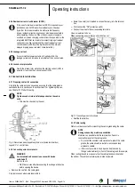
1.10 Transport
NOTE
Transporting the device
→ Transport the device in its original packaging only.
→ Secure the device so it cannot slip, e.g. by using a
lashing strip.
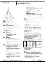
WARNING
Transporting the fan
Injuries from tipping or slipping
→ The fan is always to be transported with care and in its
original packaging.
→ If set down too hard or at an angle for example, the
impact can lead to bearing damage or deformation of the
frame or impeller.
→ It must be ensured that the fans cannot tip over during
transportation and handling.
→ Secure the fan(s) with appropriate equipment such as a
lashing strip so that nothing can slip or tip, especially when
stacking multiple fans.
→ Also make allowance for possible wind forces.
Item no. 50894-5-9970 · ENU · Change 202992 · Approved 2019-03-28 · Page 2 / 14
ebm-papst Mulfingen GmbH & Co. KG · Bachmühle 2 · D-74673 Mulfingen · Phone +49 (0) 7938 81-0 · Fax +49 (0) 7938 81-110 · [email protected] · www.ebmpapst.com


