

Operating instructions
D3G146-LV13-01
Translation of the original operating instructions
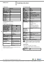
3.2 Nominal data
Motor
M3G055-DF
Phase
1~
Nominal voltage / VAC
230
Frequency / Hz
50/60
Method of obtaining
data
ml
Speed / min
-1
1550
Power consumption / W
167
Current draw / A
1.3
Min. back pressure / Pa
0
Min. ambient
temperature / °C
-25
Max. ambient
temperature / °C
50
ml = Max. load · me = Max. efficiency · fa = Free air
cs = Customer specification · ce = Customer equipment
Subject to change
3.3 Data according to ErP Directive
Actual
Req. 2015
01 Overall efficiency η
es
/ %
37.8
32.6
02 Measurement category
A
03 Efficiency category
Static
04 Efficiency grade N
49.2
44
05 Variable speed drive
Yes
06 Year of manufacture
The year of manufacture is specified on the
product's rating label.
07 Manufacturer
ebm-papst Mulfingen GmbH & Co. KG
Amtsgericht (court of registration) Stuttgart ·
HRA 590344
D-74673 Mulfingen
08 Type
D3G146-LV13-01
09 Power consumption P
ed
/ kW
0.16
09 Air flow q
v
/ m³/h
600
09 Pressure increase total p
sf
/
Pa
334
10 Speed n / min
-1
2455
11 Specific ratio
*
1.00
12 Recycling/disposal
Information on recycling and disposal is
provided in the operating instructions.
13 Maintenance
Information on installation, operation and
maintenance is provided in the operating
instructions.
14 Additional components
Components used to calculate the energy
efficiency that are not apparent from the
measurement category are detailed in the
CE declaration.
*
Specific ratio = 1 + p
fs
/ 100 000 Pa
Data obtained at optimum efficiency level. The ErP data is determined using a motor-impeller
combination in a standardized measurement setup.
3.4 Technical description
Weight
2.9 kg
Fan size
146 mm
Rotor surface
Galvanized
Electronics housing
material
PP plastic
Impeller material
Sheet steel, galvanized
Housing material
PP plastic
Motor suspension
Motor vibration-damped on both sides
Direction of rotation
Counterclockwise, viewed toward rotor
Degree of protection
Motor IP54, electronics IP20
Insulation class
"F"
Installation position
Any
Condensation
drainage holes
None, open rotor
Mode
S1
Motor bearing
Ball bearing
Technical features
- Output 10 VDC, max. 1.1 mA
- Tach output
- Motor current limitation
- Soft start
- Control input 0-10 VDC / PWM
- Control interface with SELV potential
safely disconnected from supply
- Thermal overload protection for motor
Touch current
according to IEC
60990 (measuring
circuit Fig. 4, TN
system)
<= 3.5 mA
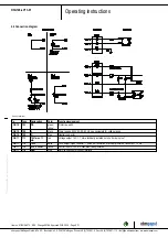
Electrical hookup
With plug
Motor protection
Thermal overload protector (TOP)
internally connected
with cable
Variable
Protection class
I (with customer connection of protective
earth)
Conformity with
standards
EN 60335-1; CE
Approval
UL 2111; CSA C22.2 No. 77
With regard to cyclic speed loads, note that the rotating parts of
the device are designed for a maximum of one million load
cycles. If you have special questions, consult ebm-papst for
support.
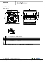
3.5 Mounting data
For screw clearance, see Chapter 3.1 Product drawing
;
Secure the screws against unintentional loosening (e.g. use self-
locking screws).
Strength class of
screws
8.8
Any further mounting data required can be taken from the product drawing.
Item no. 51144-5-9970 · ENU · Change 89188 · Approved 2016-04-18 · Page 5 / 11
ebm-papst Mulfingen GmbH & Co. KG · Bachmühle 2 · D-74673 Mulfingen · Phone +49 (0) 7938 81-0 · Fax +49 (0) 7938 81-110 · [email protected] · www.ebmpapst.com


