


20
Rev
10/2018
Operating, Installation, and Maintenance
Troubleshooting
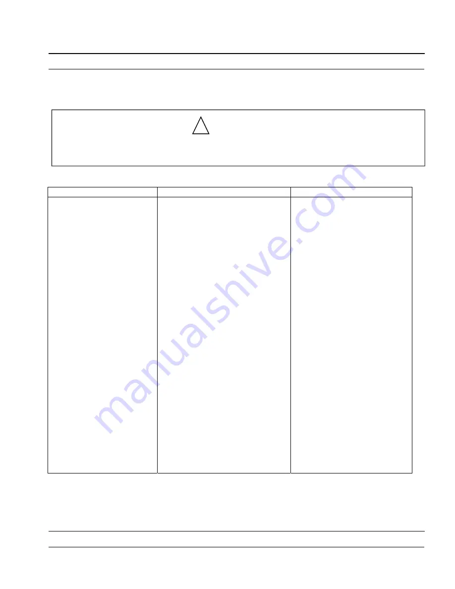
Trouble
Possible Cause
Probable Remedy
Motor Fails to Start
Loss of supply voltage
Pump motor branch circuit breaker
open or tripped
Overload trips are open
Defective starter
Loose or poor connections in control
circuit
Poor contact
Open line circuit in control panel
Leads improperly connected
Defective motor
Check voltage across all phases
above circuit breakers
Check voltage below circuit
breakers (all phases) with circuit
breakers closed
Push reset button
Select manual operation and
check voltage across starter coil.
If correct voltage is measured and
starter is not energized, coil is
defective. If no voltage is
measured, control circuit is open.
(Also check with switch in AUTO)
Make visual inspection of all
connections in control circuit, or
make spot circuit checks
Open circuit breaker, close
magnetic switch by hand and
examine contactors and springs
Check voltage at T1-T2-T3; check
magnetic contactor
Check lead numbers and
connections
Repair or replace motor
Operating, Installation, and Maintenance
WARNING
Service Work
Only certified personnel should perform service work on these pumps and motors.
!