background image


CD425 OWNERS MANUAL 

Drawing No.  :-  TPC252 
Issue :- 

Date :- 

13/10/03

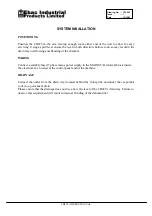
SYSTEM INSALLATION 


POSITIONING 
 

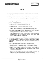
Position the CD425 in the area leaving enough room either end of the unit to allow for easy 
servicing. Using a spirit level ensure the level in both direction. Failure to do so may result in the 
drain tray overflowing and flooding of the chamber. 

 
WIRING 
 

Connect a suitably fused 3 phase mains power supply to the MAINS T/B terminal block inside 
the electrical box located at the control panel end of the machine. 

 
DRAINAGE 
 

Connect the outlet from the drain tray (located behind the front grille and under the evaporator 
coils) to a permanent drain. 
Please ensure that the drainage does not rise above the level of the CD425’s drain tray. Failure to 
observe this requirement will result in internal flooding of the dehumidifier.

Summary of Contents for CD425

Page 1: ...2 Issue 1 Date 13 10 03 EBAC MODEL CD425 1018110 INDUSTRIAL DEHUMIDIFIER OWNER S MANUAL Ebac Industrial Products Inc 700 Thimble Shoals Blvd Suite 109 Newport News VA 23606 2575 Tel 757 873 6800 Fax 7...

Page 2: ...drain tray for collecting and disposing of condensed moisture f A cabinet to house the above components The fan draws the moist air through the evaporator coils which cools the air below its dew poin...

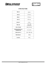
Page 3: ...1 Date 13 10 03 SPECIFICATIONS MODEL CD425 HEIGHT 1190 mm WIDTH 1100 mm DEPTH 460 mm WEIGHT 160 kg AIRFLOW 1750 CFM 3000M Hr TOTAL POWER 6 0Kw MAX MAXIMUM OPERATING TEMPERATURE 35 C 95 F POWER SUPPLY...

Page 4: ...Remove the front cover b Check the actual relative humidity inside the area c Set humidity control to a LOWER value than the actual relative humidity d After approximately 6 minutes check the compres...

Page 5: ...ng and flooding of the chamber WIRING Connect a suitably fused 3 phase mains power supply to the MAINS T B terminal block inside the electrical box located at the control panel end of the machine DRAI...

Page 6: ...for life and therefore does not need oiling 3 To check the refrigerant charge run the unit for 15 minutes and briefly remove the cover The evaporator coil should be evenly frost coated across its surf...

Page 7: ...of the refrigerant compressor The charging stub should be crimped and rebrazed after servicing NEVER allow permanent service valves to be fitted to any part of the circuit Service valves may leak cau...

Page 8: ...breaker Little or no water extraction 1 Insufficient air movement 2 Compressor fault 3 Loss of refrigerant gas 4 Blocked filter dryer 1 Check all of the above 2 Contact the Factory Service Center 3 C...

Page 9: ...5kg Drain Tube 2014315 3 meters 3 8 Copper Tube 3014203 2 meters 1 2 Copper Tube 3014204 2 meters 5 8 Copper Tube 3014205 2 meters Cork Tape 3100223 1 2 Roll Fan Motor 3030140 1 Axial Fan 3010119 1 So...

Page 10: ...ANY WRITTEN OR IMPLIED WARRANTY WITH RESPECT TO THE FOREGOING DESCRIBED MERCHANDISE For Your Records Model ____________________ S N ______________________ Date Received ______________ SAVE THIS SECTI...

Reviews: