background image

KF760 Series Rigging Procedures  PRELIMINARY DRAFT -- 21 Aug 01

KF760 Series Rigging Procedures  PRELIMINARY DRAFT -- 21 Aug 01   Page 25 of 29


8.  Reinsert the connecting pins back in the holes from where they were removed from the bottom most
flown enclosure.  Push the palleted KF761 aside.

9.  Repeat the above steps for additional KF761s.

2.4.4

KF760s


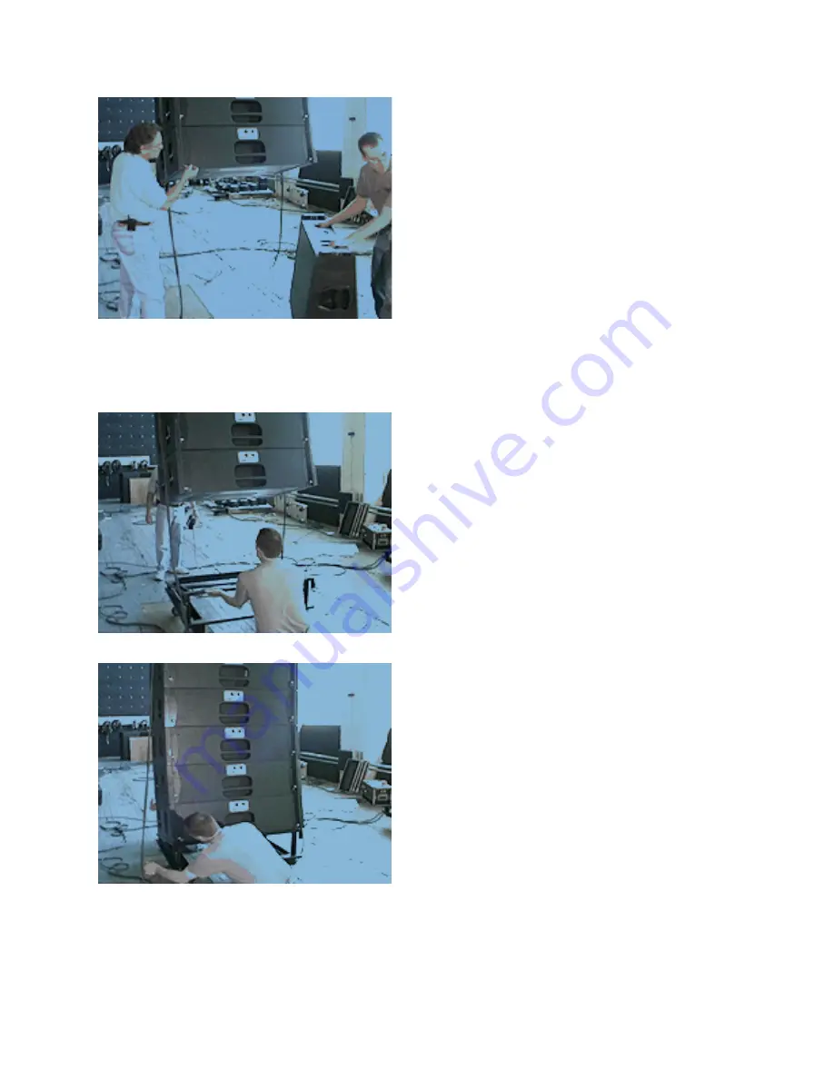
1.  Position an empty KF760 pallet under the array.


2.  Drop the array onto the pallet until any rear splays close up and weight is just off the chain motors. 
Ensure that the alignment pads on the bottom of the KF760 mate with their slots on the top of the caster
pallet  rails.    Ensure  the  Hinge  Tubes  on  the  bottommost  enclosure  mate  with  the  hinge  Tubes  on  the
pallet.

Summary of Contents for KF760

Page 1: ...K F 7 6 0 S E R I E S R I G G I N G G U I D E...

Page 2: ...re that the connecting pins extend fully through the holes and are fully locked The casters are replaceable allowing use of different types of casters or wheel materials or wheel sizes as needed for t...

Page 3: ...be available where they are needed for the purposes listed The only exceptions are the two extra short connecting pins shipped with each enclosure used for locking the hinges when the Pull Back Bar i...

Page 4: ...y to achieve the correct hang angle Advantages The pull back motor will have a much less load on it than when using the Tail piece The number of degrees of pull back is not limited Disadvantage The pu...

Page 5: ...rmally gravity keeps the rears of splayed enclosures apart thus maintaining the splay When a Pull Back Bar is used it creates an upward force on the rear of the enclosures tending to push the rears of...

Page 6: ...the chain motors for attachment ot the Fly Bar Hoist Rings 3 If the Fly Bar was transported attached to palleted KF760s then attach the chain motors to the Fly Bar and skip the next steps 4 If the Fly...

Page 7: ...e Top hole tight packed Center Hole 1 1 2 splay Bottom hole 3 splay Ensure that the connecting pins extend fully through the hinges and Hinge Tubes and are fully locked 5 Ensure that all hinges on the...

Page 8: ...ur connecting pins in the bottom enclosure Hinge Tubes 8 Fly the first four enclosures to an appropriate working height for the next step and push the KF760 pallet aside Later this will be used as a K...

Page 9: ...ges and Hinge Tubes and are fully locked 3 If Using the Pull Back Bar not shown If the Pull Back Bar is to be used the rear hinges on any splayed enclosures must be locked in position to prevent the h...

Page 10: ...ing pins Insert the four connecting pins in the bottom enclosure Hinge Tubes 6 Bring in flown enclosures to within about 1in 25 cm of the front top of palleted enclosures 7 Slide up the two front hing...

Page 11: ...front hinges Engage the two front hinges in their fully extended position into the Hinge Tubes of the flown enclosure and secure using a short connecting pin in each 10 Land the flown enclosures on th...

Page 12: ...r is to be used the rear hinges on any splayed enclosures must be locked in position to prevent the hinges from moving down into their own Hinge Tubes when the pull back force is applied To lock the h...

Page 13: ...s to an appropriate working height for the next step 2 3 4 First KF761 1 Bring in first pallet with a KF761 2 Remove the KF761 from the pallet and place flat on a KF760 pallet removed above from the K...

Page 14: ...bring in the flown enclosures to within 1 of front top of the palleted KF761 enclosure 5 Remove the two short connecting pins stored in the KF761 front Hinge Tubes Slide up the two front hinges of the...

Page 15: ...ted KF761 enclosure 7 Remove the two short connecting pins temporarily inserted into the front hinges Engage the two front hinges in their fully extended position into the Hinge Tubes of the flown enc...

Page 16: ...osure and a KF761 enclosure together always use the second hole in the KF760 Hinge tube for connecting the KF761 This sets the splay angle between the acoustic axis of the KF760 and KF761 at 9 This pr...

Page 17: ...l enclosures to an appropriate working height for the next step 2 3 4 Second And Subsequent KF761s 1 Bring in the second KF761 2 Remove the KF761 from the pallet and place flat on an empty KF760 palle...

Page 18: ...bring in the flown enclosures to within 1 in 25 mm of front top of the palleted KF761 enclosure 5 Remove the two short connecting pins stored in the KF761 front Hinge Tubes Slide up the two front hing...

Page 19: ...ted KF761 enclosure 7 Remove the two short connecting pins temporarily inserted into the front hinges Engage the two front hinges in their fully extended position into the Hinge Tubes of the flown enc...

Page 20: ...osure and a KF761 enclosure together always use the second hole in the KF760 Hinge tube for connecting the KF761 This sets the splay angle between the acoustic axis of the KF760 and KF761 at 9 This pr...

Page 21: ...bottommost enclosure Pin each hinge to the uppermost hole in the enclosure Hinge Tube using a short connecting pin 2 Attach the pull back chain motor to the hoisting ring on the Pull back Bar 2 3 6 La...

Page 22: ...to swing down on its rear hinges with its face parallel to the floor and above the level of its pallet 2 Position an empty KF761 pallet under the array Not Shown 3 Remove any hinge locking pins from t...

Page 23: ...the KF761 rests on its pallet with the weight just off the chain motors 6 Remove the rear pins connecting the KF761 to the enclosure above it Bump out the array to allow the next KF761 to swing down...

Page 24: ...1 to swing down on its rear hinges with its face parallel to the floor and above the level of its pallet 2 Position an empty KF761 pallet under the array Not Shown 3 Remove any hinge locking pins from...

Page 25: ...5 While positioning the pallet bump the array down so the face of the KF761 rests on its pallet with the weight just off the chain motors 6 Remove the rear pins connecting the KF761 to the enclosure a...

Page 26: ...ush the palleted KF761 aside 9 Repeat the above steps for additional KF761s 2 4 4 KF760s 1 Position an empty KF760 pallet under the array 2 Drop the array onto the pallet until any rear splays close u...

Page 27: ...g pins for this should have been stored in the bottom of the KF760 4 Check for and remove any hinge locking pins from the rear Hinge Tubes and put aside for loose storage Remove the front and rear con...

Page 28: ...r additional KF761s 2 4 5 Last Group Of KF760S 239 to 249 1 Position an empty KF760 pallet under the array 2 Drop the array onto the pallet until any rear splays close up and weight is just off the ch...

Page 29: ...Check for and remove any hinge locking pins from the rear Hinge Tubes and put aside for loose storage 2 4 6 Fly Bar Fly Bar Stays with Enclosures 1 If not already done lock the four hinges of the top...

Page 30: ...nto the enclosure s Hinge Tubes 2 Reinsert the removed connecting pins into the holes on the Fly Bar from which they were removed 3 Fly out the Fly Bar 4 Push the pallet loaded with the four KF760s ou...

Page 31: ...2 5013 508 234 6158 fax 508 234 8251 web www eaw com T h e L a w s o f P h y s i c s T h e A r t o f L i s t e n i n g EAW is the worldwide technological and market leader in the design and manufactur...

Reviews: