EAW AC6 Quick Start Manual Download Page 9

Tel 800 992 5013 / +1 508 234 6158  

|

  www.eaw.com

9

AC6 

Quickstart Guide

It is possible to edit the X,Y,Z physical location, 

Min Trim, Max Hang and Aim Angle in the 

Properties pane while that Array is selected.

If a venue and arrays have been created in 

Resolution, then representations of the Arrays 

and Modules in the model will be displayed in 

the Network Configuration View as grey boxes. 

Each module in the array will have a small 

indicator square that reports each module’s 

status.

• A question mark indicates that no 

physical module has been associated 

with the module in the model.

• A Yellow box indicates a module that has 

gone offline.

• A Red box indicates a module previously 

assigned that was not found upon 

reconnecting to the Network. 

• A box that occasionally flashes Green 

indicates the module is successfully 

communicating with Resolution.

Unassigned modeled Arrays will have the list 

of modules or loudspeakers included in the 

Array while non-arrayed loudspeakers will 

be shown as individual boxes with only one 

device listed. Arrays will be shown with the 

modules in Columns and the meters.

A physical AC6 Array in the Online Devices list 

can be assigned or associated with a modeled 

Array in the model by simply clicking on the 

Array in the list and dragging it on to the 

appropriate modeled Array. 

Note: the physical Array and modeled Array must 

include the same quantity and arrangement of 

modules). 

Assign all physical Arrays to modeled Arrays 

until all Arrays have been assigned.

Managing AC6 in Resolution

Once a physical Array has been associated 

with a modeled Array, the individual modules 

listed in the Array will be graphically arranged 

in Columns and a small square “indicator 

light” for each module. These indicators 

will periodically flash green to confirm 

that Resolution 2 has established active 

communications with each Anya module. 

Clicking an Array in the Network Configuration 

Desktop will display it’s properties in the 

Properties View window (if the Properties 

View window is opened) and can be edited as 

explained in the Properties View chapter.

Array Processing can be displayed and edited 

in real-time by double-clicking the EQ graph at 

the top of the Properties View window. 

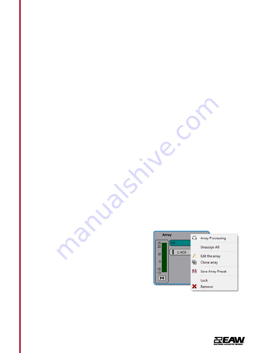
Right clicking an Array will open a menu with 

options to open Array Processing, Unassign 

All, Edit the array (which will launch the Array 

Assistant), Clone the array, Save Array Preset, 

Lock array movement, or Remove array. These 

mirror functions available in the Project 

Explorer and Properties panes. 

Summary of Contents for AC6

Page 1: ...Quickstart Guide AC6...

Page 2: ...workers associated with system deployment enjoy a working understanding of the critical life safety issues associated with large scale sound system use Internal Processing Amplification As is true of...

Page 3: ...e in venue optimization supplemental software such as Rational Acoustics Smaart may be desired but this is not required for basic system operation Always ensure that your EAW Resolution software and A...

Page 4: ...me directivity from the same physical length regardless of whether this length is made up of 8 10 12 or 15 components The determining factor is the length of the array itself and how that length affec...

Page 5: ...rray length must be considered Venue Design Examples The following section contains a variety of venue examples with recommended systems for each The venue type capacity recommended system size and ex...

Page 6: ...erspective THEATER 70 X 75 SEATING CAPACITY 670 PEOPLE Equipment List 4x AC6 2x SB828P Plan Elevation Perspective AUDITORIUM 70 X 80 SEATING CAPACITY 510 Equipment List 4x AC6 2x SBX218 1x MKD1096 4x...

Page 7: ...e computer is connected to the same Ethernet network as the networked loudspeaker system Communications is established by clicking Network on the Menu bar and selecting Connect Resolution 2 will then...

Page 8: ...and connecting to the system This will ensure you know how the Arrays will need to be configured However this is not required and you can simply fly the arrays and connect Resolution 2 to your system...

Page 9: ...be assigned or associated with a modeled Array in the model by simply clicking on the Array in the list and dragging it on to the appropriate modeled Array Note the physical Array and modeled Array m...

Page 10: ...AC6 Quickstart Guide Double clicking the teal input assignment button will open the Array Configuration dialog Right clicking a module in an Array will open a menu with options to Insert Item Above I...

Page 11: ...module will open the Diagnostics Window for that module Updating Firmware on AC6 NOTE Before starting Firmware update please turn the Windows Firewall off NOTE It is highly recommended you run the fir...

Page 12: ...Tel 800 992 5013 1 508 234 6158 www eaw com 12 AC6 Quickstart Guide Select the firmware file eawfw in C ProgramData EAW Resolution Windows must be set to show hidden files and folders...

Page 13: ...ay result in damage injury or death 1 Read these instructions 2 Keep these instructions 3 Heed all warnings 4 Follow all instructions 5 Clean only with a dry cloth 6 Install loudspeaker in accordance...

Page 14: ...ounted spacing should be 39 0 990 6mm from centerline to centerline This can be measured from bracket top to bracket top d Product is designed for vertical mounting only Use of level is encouraged to...

Page 15: ...posite direction For symmetrical L R setups the bracket will mount in mirror fashion c Locate the flytrack studs attached to the bracket inside the flytrack on the back of the cabinet The two locating...

Page 16: ...alog audio and dry contacts can be looped from either end Refer to user manual for more information c Starting from the bottom of the array and moving to the top mount each AC6 to the respective wall...

Page 17: ...M6x20 screws attach the cover to the wall bracket to hide the hinge mechanism Do not overtighten Panned wall bracket Flush Mount Bracket Instructions Tools needed 10mm wrench or hex driver 4mm allen...

Page 18: ...e rated at 175lb 80kg b Mark the wall or structure where brackets will be mounted Refer to the included customer drawing 2071359 CD for mounting pattern Use the points that provide the highest amount...

Page 19: ...must be mounted in the orientation in which they should be connected Either from the top or from the left or right side c Locate the flytrack studs attached to the bracket inside the flytrack on the b...

Page 20: ...s d If WP covers are being used install the covers at this stage e Using two people line up the flush wall mount to the AC6 bracket then slide into place f The button head screws M6x35 on the cabinet...

Page 21: ...k to Stinger in order to array straight with no tilt angle a M10 bolts or pins for portable use 2 Using steps above attach AC6 cabinet bracket for flush mount 3 Attach stinger to AC6 using M10 bolts I...

Page 22: ...Tel 800 992 5013 1 508 234 6158 www eaw com 22 AC6 Quickstart Guide 4 Attach 1 2 shackle to stinger or mohawk 5 Suspend AC6...

Page 23: ...ckstart Guide Pole Mount 1 Place AC6 Upside down 2 Remove M5 Screws from bottom 3 Attach Pole cup adapter with M5x20 screws lock washer and large flat washer 4 Using 2 people place AC6 on speaker stan...

Page 24: ...d and discarded e Inspect hardware securing the u bracket to the mounting surface for corrosion or looseness Tighten loose hardware and consider installing hardware locking methods Replace and discard...

Page 25: ...of AC6 modules Location and quantity of audio network and power cabling One end of each cable must be left unterminated to pass through the knockouts Identify if covers will be fitted before or after...

Page 26: ...d remove the rest of the knockout by hand if necessary If burrs remain remove them with a countersink or deburring tool Note knockout size is for reference only and must be drilled out Joint Cover eac...

Reviews: