65A7320H01
1 of 41
W-VACiMB FIXED SECONDARY
TERMINAL BLOCK OEM
CONVERSION TYPE #1
PUSH ON TYPE TERMINAL BLOCK
Page 1: ...65A7320H01 1 of 41 W VACiMB FIXED SECONDARY TERMINAL BLOCK OEM CONVERSION TYPE 1 PUSH ON TYPE TERMINAL BLOCK...
Page 2: ...eplace it with a Push On type terminal block that contains the following connections Refer to Figure 29 o Spring Charging Circuit Uses secondary connector pins 25 35 o 1 Shunt Open Circuit Trip Coil U...
Page 3: ...Coil Charging Motor and Trip Coil will share a common return See Appendix A You may choose to not install the jumpers for more circuit flexibility Use appendices A through F for additional informatio...
Page 4: ...0 2 End Cap www ab com 1492 EAJ35 3 49 Each 3 Feet Translucent Wire Sleeving www McMaster com 7432K741 8 97 per foot 5 Zip Tie www McMaster com 7130K19 3 78 per 100 5 Zip Tie Holder www McMaster com 7...
Page 5: ...65A7320H01 5 of 41 Gray Terminal Divider End Cap Translucent Wire Sleeving Zip Tie Zip Tie Holder Electrical Tape Arc Protect Tape...
Page 6: ...65A7320H01 6 of 41 PROCEDURE Step 1 Locate the secondary control power wiring terminal box on the breaker Figure 1 Breaker side secondary Terminal Box...
Page 7: ...65A7320H01 7 of 41 Step 2 Insert flat head screwdriver into the two clips to release the front cover Figure 2 Schematic of the how to remove the front cover on the secondary...
Page 8: ...y pressing the male pin remover into a pin slot and pushing hard to unseat the pin Once the pin has been unseated push from the opposite side of the secondary connector to pull the pin out of its slot...
Page 9: ...9 of 41 Figure 3b Press the male pin remover in hard to unseat the pin Figure 3c Once unseated by the male pin remover push on the pin from the opposite side to get the pin out of the slot Repeat for...
Page 10: ...all pins have been taken out of their slots remove the secondary connector and rubber tubing Discard if desired Figure 4 Remove the gray rubber tubing and secondary connector they will not be used Ru...
Page 11: ...of 41 Step 5 Separate the 14 wires needed for the secondary terminal block from the rest of the wires and set them aside See appendix A for a listing of the necessary wires Figure 5 Separating the 14...
Page 12: ...12 of 41 Step 6 Pull the unnecessary wires through the hole in the top of the breaker These wires will be secured inside the breaker in the proceeding steps Figure 6 Pull out the unnecessary wires 14...
Page 13: ...3 of 41 Step 7 Wrap about 22 inches of transparent protective covering around these unnecessary wires These wires that are unused will be secured inside of the breaker Figure 7 Transparent protective...
Page 14: ...65A7320H01 14 of 41 Step 8 If too long cut the transparent protective wiring cover two inches from the end of these unnecessary wires Figure 8 Removal of excessive wiring cover...
Page 15: ...65A7320H01 15 of 41 Step 9 Cut an 8 inch section of the fire retardant arc protective tape Figure 9 Cutting an 8 inch section of arc protective tape...
Page 16: ...01 16 of 41 Step 10 Wrap the arc protective tape around the exposed portion of the unused wires Then secure this protective tape with the electrical tape Figure 10 Wrapping the unused wires in electri...
Page 17: ...65A7320H01 17 of 41 Step 11 Wrap the unused wires completely with electrical tape Figure 11 Unused wires completely covered...
Page 18: ...ow secure the unused wires inside the breaker Place 2 cable tie holders on the inside wall of the breaker spring side Position them about three inches from each other and a half inch from the edge Fig...
Page 19: ...65A7320H01 19 of 41 Step 13 Insert cable ties through the inslots of the tie holders to secure the unused wires Figure 13 Securing of the unused wires...
Page 20: ...4 Place another cable tie holder as shown closer to the back of the breaker to hold the end of the unused wire bundle Zip tie the bundle to the cable tie holder Figure 14 Securing of the wires to avoi...
Page 21: ...d be clipped Figure 15a left Use three zip ties to secure the unused wires to the inner wall Figure 15b right Wires are secured from both the closing and open spring assemblies In Process Quality Chec...
Page 22: ...of 41 Step 16 Wrap transparent wiring cover around the 14 wires used for the terminal blocks The wiring cover should span roughly eight inches Figure 16 Wrapping of the transparent wire covering on t...
Page 23: ...white and 6 grey terminal blocks onto the DIN Rail Attach the 4 grey dividers onto each set of colored terminal blocks and put on the 2 end caps as shown below Figures 17a 17b Attachment of the block...
Page 24: ...ep 18 Squish all pieces together so there are no gaps and fasten both grey end caps to the DIN Rail as shown by using a flathead screwdriver Figures 18a 18b Mounting and fastening of the end terminal...
Page 25: ...f 41 Step 19 Unfasten the bolt on the top center of the breaker that helps secure the mechanism in place using a 10 mm wrench Figure 19 Temporary removal of the center bolt It will be used for mountin...
Page 26: ...65A7320H01 26 of 41 Step 20 Unfasten this bolt on the underside of the top of the breaker ground terminal connection bolt using an 8 mm wrench Figure 20 Removal of the bolt...
Page 27: ...e DIN Rail and block terminals onto the top of the breaker using the bolts removed in steps 19 and 20 Remember to reconnect the grounding wire on the inside of the breaker Figure 20 Figure 21 Securing...
Page 28: ...65A7320H01 28 of 41 Step 22 Slide the white labels on the wires back until they reach the transparent wire cover Figure 22 Sliding the white labels back...
Page 29: ...ess wire on each wire by lining up the wire with the screw hole of the terminal slot designated for that wire See Appendix A The wires will increase in length as you go down the DIN Rail from left to...
Page 30: ...65A7320H01 30 of 41 Step 24 Use wire strippers to strip all 14 ends approximately 10 mm in length 14 Gauge Figure 24 Stripping the wires...
Page 31: ...65A7320H01 31 of 41 Step 25 Secure each wire in position by fastening each screw as shown using a small flathead screw driver Figure 25 Securing of the wires...
Page 32: ...1 32 of 41 Step 26 Install the 2 four pole jumpers on the red and white terminals Make sure to tighten all screws so all terminals have a solid connection the jumper Figures 26a 26b Installing the two...
Page 33: ...ep 27 Attach two cable tie holders to the top of the breaker and secure the wires with cable ties Place the cable tie holders about two inches from each other as shown Figure 27 Securing of the wires...
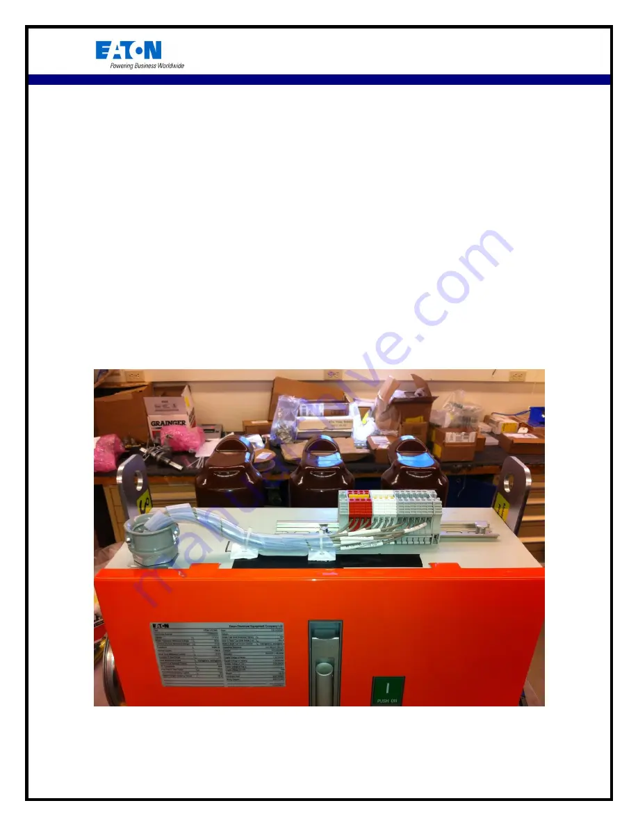
Page 34: ...65A7320H01 34 of 41 FINAL RESULT...
Page 35: ...y tightened Electrically test the operation of the breaker to make sure the modifications were correctly done and that the breaker properly operates Electrically operate the breaker five times for a c...
Page 36: ...rn Lo 6 P2 X11 14 U2 2 Close Coil Return Lo 7 F22 M1 2 22 X11 35 Motor Return Lo 8 C2 Q1 1 2 X11 30 Trip Coil Return Lo 9 H3 X11 2 Y6 1 UVR Power Supply Hi 10 P1 X11 4 U2 1 Close Coil Power Supply Hi...
Page 37: ...65A7320H01 37 of 41 Appendix B Reference wiring variations Figure 29 Graphical schematic of terminal assembly...
Page 38: ...65A7320H01 38 of 41 Appendix C DIN Rail...
Page 39: ...65A7320H01 39 of 41 Appendix D W VACiMB Wiring Diagram...
Page 40: ...65A7320H01 40 of 41 Appendix E New Overall Breaker Dimensions...
Page 41: ...ay Motor NO Relay 1 NO Relay 2 NC Relay UVR Close Coil Motor Trip Coil UVR Close Coil Trip Coil NO Relay 1 NO Relay 2 NC Relay Motor NO Relay 1 NO Relay 2 NC Relay UVR Close Coil Motor Trip Coil UVR C...